
Repair
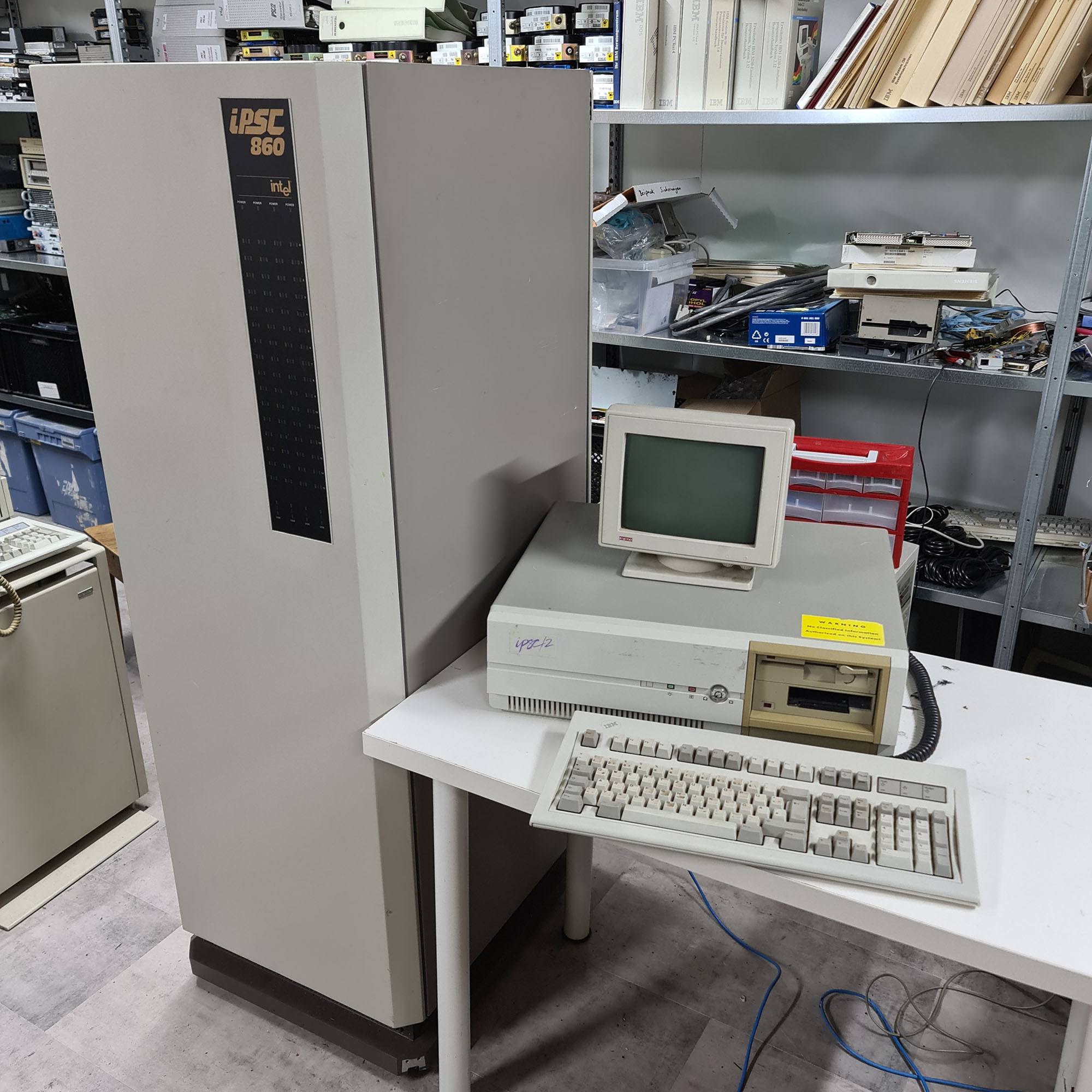
After we received an appropriate Intel SYP30 front-end (SRM), we could start thinking about getting our Intel iPSC/860 running again. The SYP-301 came with documentation and software for iPSC/2 and iPSC/860 systems, and an iPSC/2 cardcage with 8 node boards from an iPSC/2, a node board from an iPSC/860, an I/O board with SCSI controller, and a USM board.
- Details
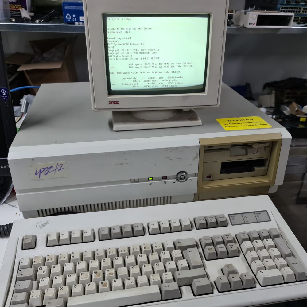
After a fair amount of work in a week's time, the Intel SYP301 that will serve as the Intel iPSC/860's SRM has booted!
- Details
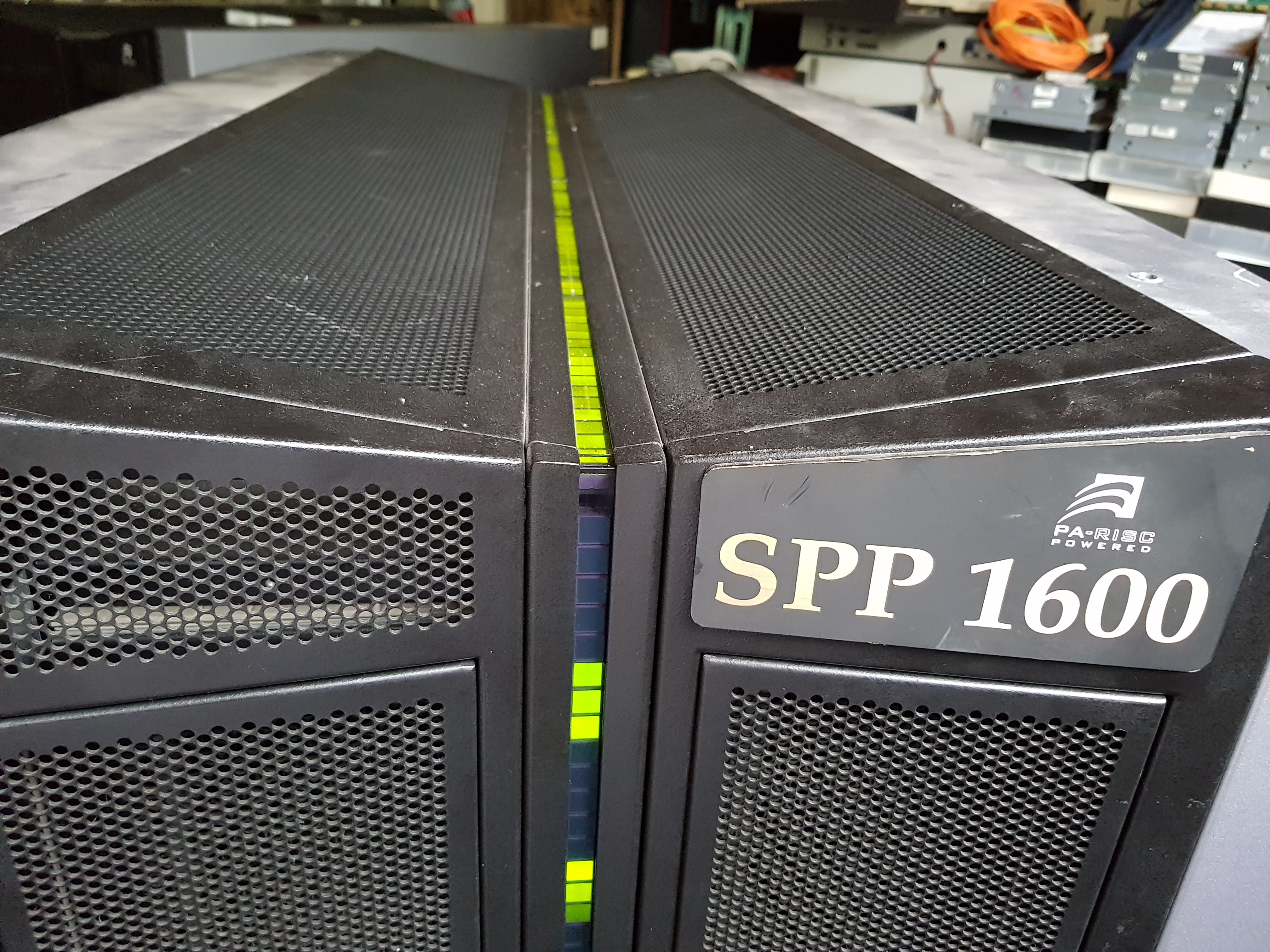
After the Arrival of the Convex SPP's, and after reading most of the hardware documentation that came with the systems, I worked mainly on the Convex Exemplar SPP-1600/XA for a couple of weekends.
- Details
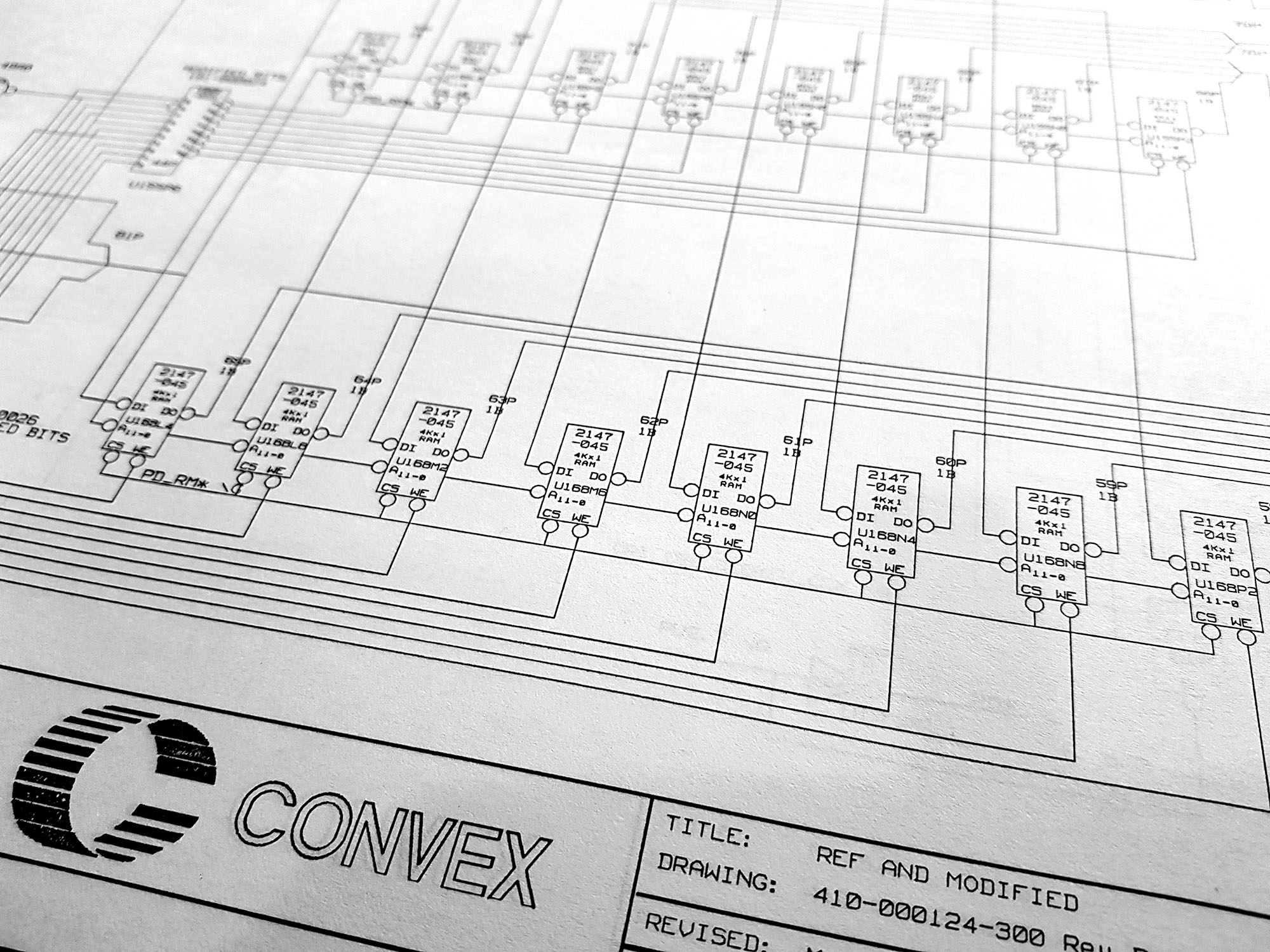 A while ago, I received a copy of the schematics for the Convex C1 Supercomputer. It took me a while to scan them all, but now that that's done, I've made them available on the Convex Documentation page.
- Details
 After the Convex C240 Arrived, and the I/O cabinets and spare parts along with it, it was time to continue work on the Convex C220 after the Initial Convex C220 Checkout.
- Details
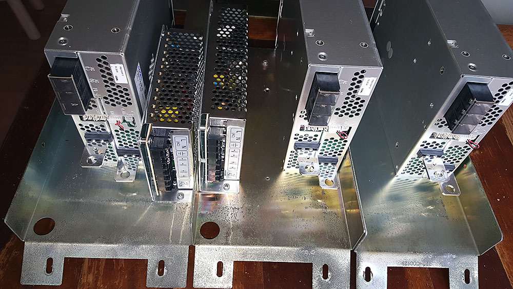
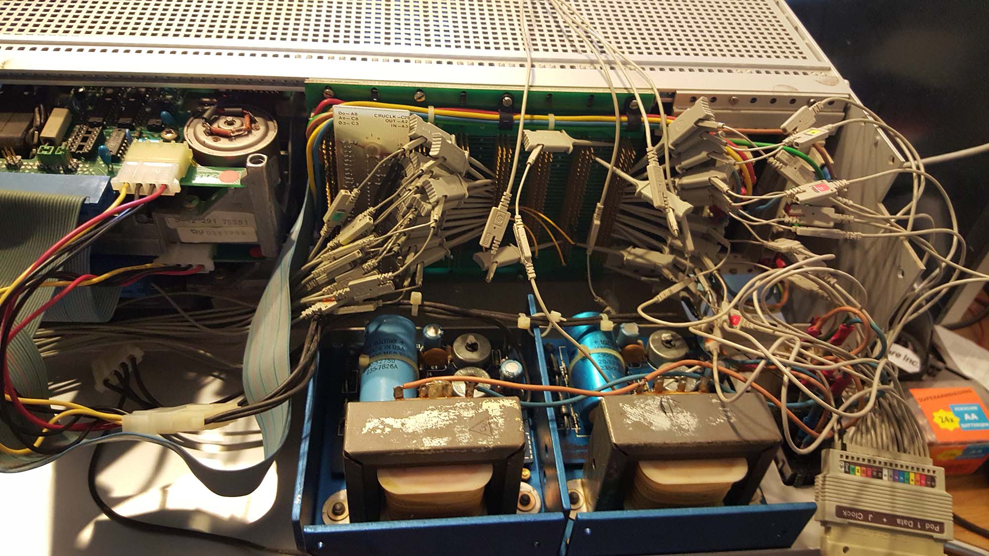
A couple of weeks ago, as I was using the Convex to debug the SMD disk emulator, the Convex started failing in its memory initialization. During my attempts to debug this new failure, there was a fairly loud bang, as one of the smoothing capacitors in one of the LH Research Super Mite power supplies exploded. I immediately hit one of the emergency power-off buttons I have installed in my lab, fearing what damage to the cpu the power supply failure might have done.
- Details
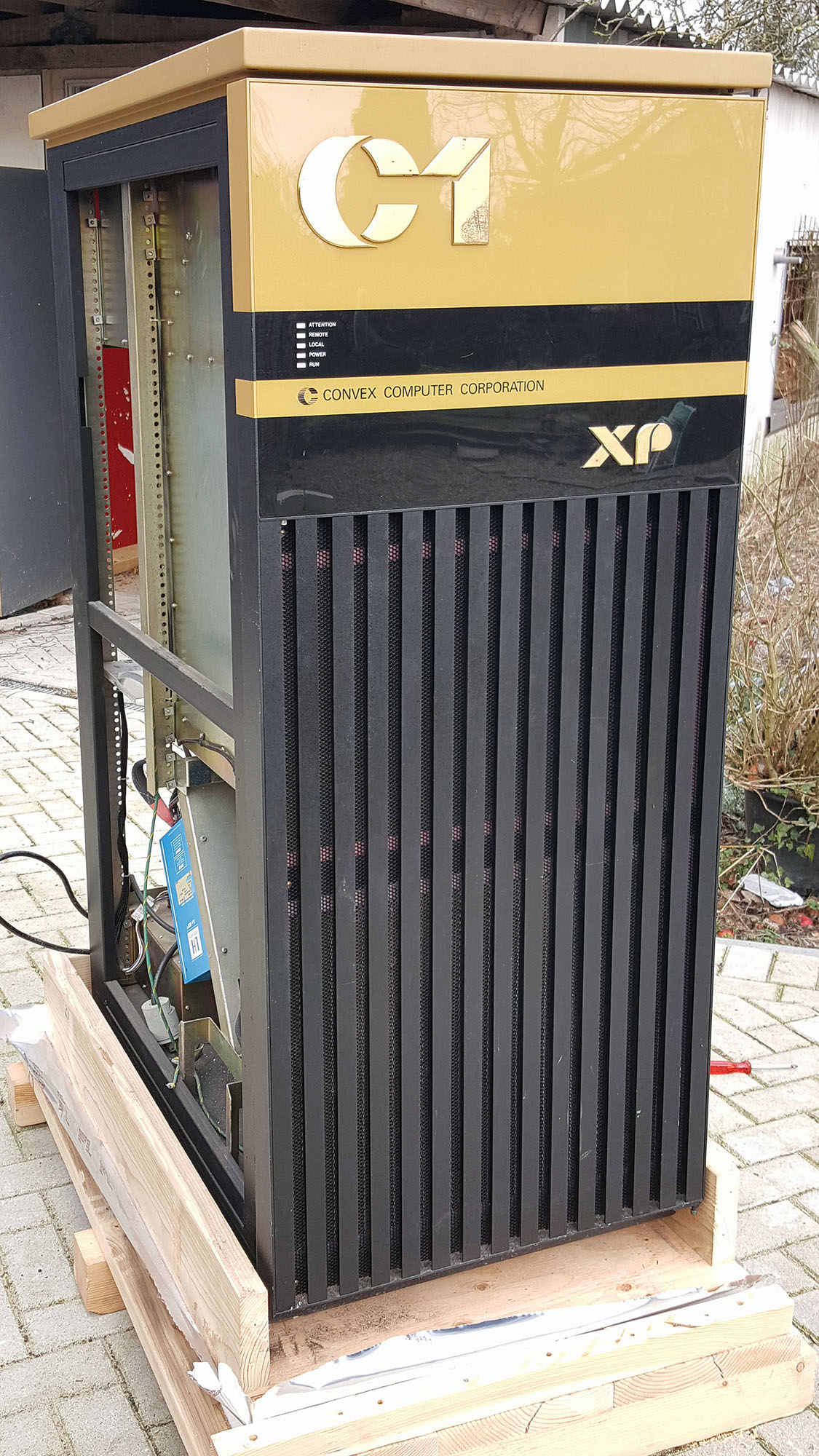
Before I can install an OS on the Convex C1 XP, three things need to happen: I need to obtain an installation tape, I need to get the tapedrive working, and I need to finish the emulated disk (Eagle Emulator). This weekend, it was time to work on the tapedrive.
- Details
So, now that we got SPU UNIX up and running on the service processor unit (see Convex C1 XP Service Processor power-on), it's time to do something with it.
The purpose of SPU UNIX is to serve as an environment to initialize the system (load microcode onto the job processor, or main CPU; initialize memory), as well as diagnose the hardware. Wil a lot of help from ex-Convex employees (a special thanks goes to Doug Hosking), I learned a lot about what can be done in this environment.
- Details
*** Updated 16-MAR-2017 *** I’ve started working on the Convexes; the first order of business on these machines (after a thorough visual inspection for things like loose wires, bent pins or bulging capacitors) is checking out the power supplies.
- Details
After my supercomputers arrived last Friday, I decided to have a look at getting the Ardent Titan going first, since that was the only system apparently complete enough to do so (the Intel iPSC/860 is missing a vital component: the SRM, a UNIX workstation that controls the rest of the system, and the Convex C1 XP and Convex C1 XL are missing the main SMD hard drives).
- Details
This TEP FTI990 initially seemed to be in good shape, however, initially I couldn't get it to boot. In the end several problems were found that conspired to prevent it from booting.
Most problems were identified by hooking the system up to a logic analyzer (my trusty HP 1660C), then following the execution of code through the ROM-based boot loader. For this, I dumped the EPROMs' contents to a file using an EPROM programmer, then hand-disassembled the relevant bits of code.
- Details
- YouTube:
After degreasing and re-lubing the I/O Selectric (using light machine oil, LSA gun oil, and lithium grease), I was more or less satisfied that turning on the power to the motor wouldn't harm the machine, so that's what I did today.
I love the sounds you can hear in this video!
- Details
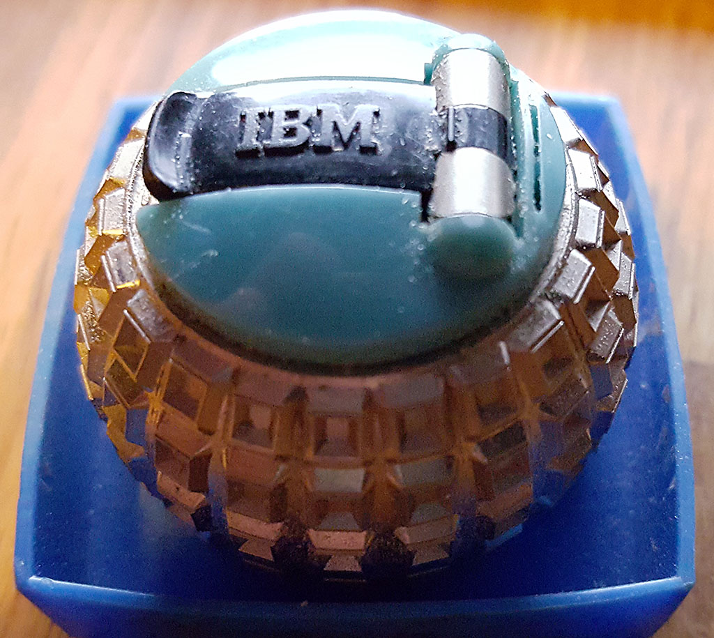
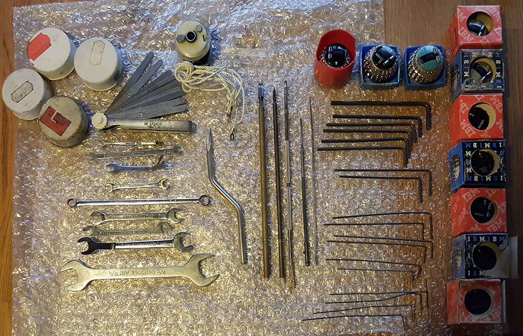
Today I received a package in the mail from a Dutch ex-IBM service technician I got to know through an advert for some golfball font elements. The package contained 9 different fonts for my Selectric, a special golfball with squares used for alignment of the machine, some spare parts, and a lot of original IBM tools for servicing the Selectrics. What a wonderful thing to receive!
The keys that look like regular Hex (or Allen) Keys, are something special, as they have grooves; I believe these are Bristol wrenches. They fit the various set screws in the Selectric. The round white boxes contain tilt and rotate tapes; unfortunately they do not contain the particular rotate tape I need right now.
- Details
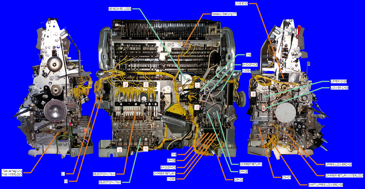
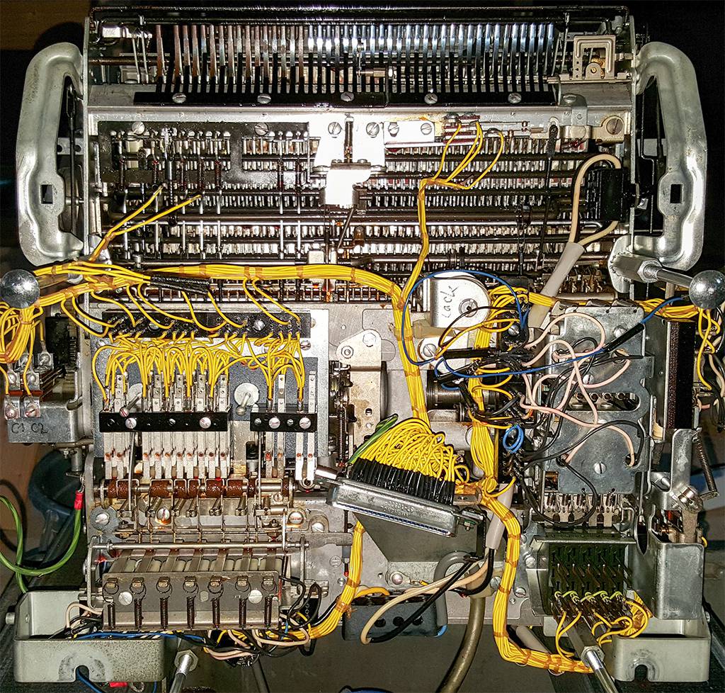
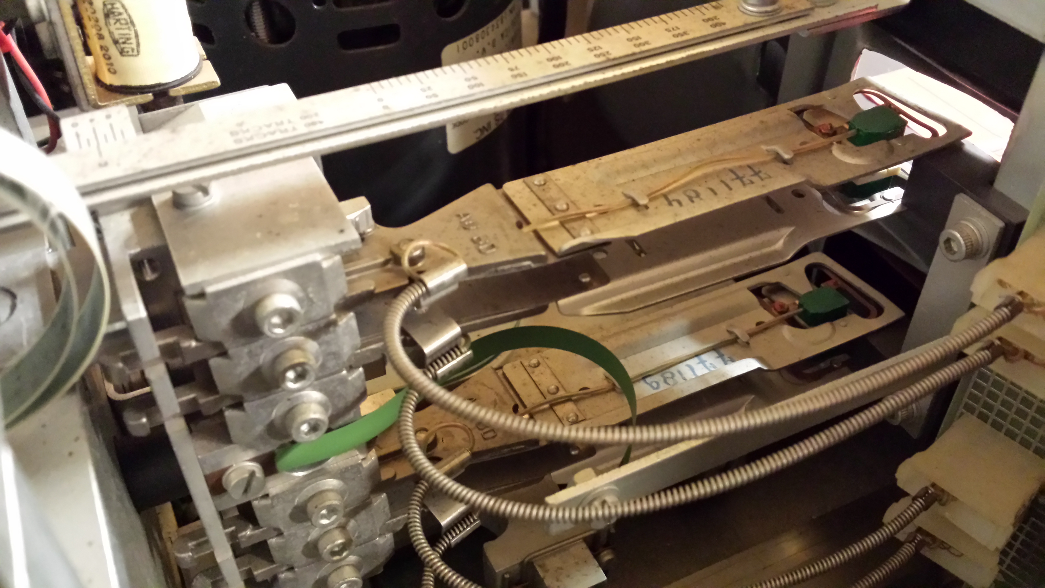
I made this diagram to easily find all the switches (orange lines), solenoids (green lines) and contack blocks (red letters).
- Details
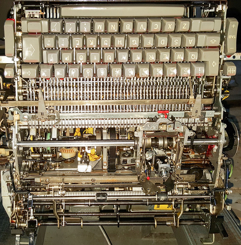
The first order of business for the I/O Selectric is a visual inspection, both in and out of its outer shell. Other than a broken right margin lever, this didn't reveal any obvious faults. In fact, the machine looks pretty clean for a 50 year old device. Of course, the nasty foam under the keys has deteriorated to the point where it crumbles into sticky goo when you touch it, but some compressed air helped to quickly blow that out of the way.
Some dust and hardened grease...
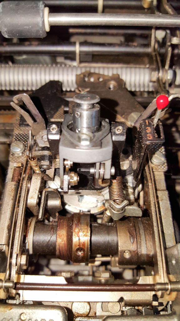
After that, it's time to fit the indispensable Hand Cycling Wheel to the right-hand side of the Operational Shaft, and try out some of the machine's operations while providing power by hand. Letting the motor run at this point would be too risky.
Overall, things seem ok; on some of the operations there's a bit of a delay, mainly due to cam followers returning to their original position sluggishly because of hardened grease and dust. Trying to half-cycle some characters revealed a more serious problem though, because while the golfball-shaped printing element was tilting correctly, it wasn't rotating very much. Further inspection showed that the rotate tape wasn't taut as it should be. The rotate tape is a very thin (0.06 mm) metal tape that pulls on a pulley to rotate the element, while a spring on the bottom of the pulley provides the necessary counter-force. Pulling on the rotate tape revealed that it had snapped into two pieces.
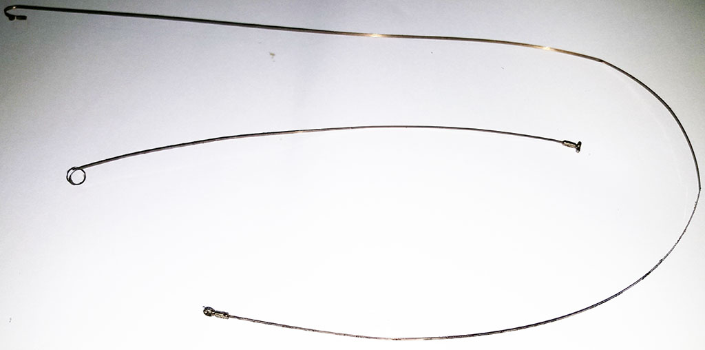
I found a supplier of these tapes in the US, but they charge an indecent amount for shipping to Europe. Fortunately, I happen to be in the US next month, so I've ordered some parts to be sent to a friend of mine there.
Until then, one thing I can do is clean the machine. The first stage of this is degreasing the machine, for which I use a spray bottle filled with Jizer, an industrial-strength automotive degreaser. I spray all parts of the machine liberally, then after letting it soak for a while, I use an assortment of small brushes to clean some of the loosened goo out, then re-spray with Jizer.
Bottom side during de-greasing
Top side during degreasing
The pink fluid in the images above is the Jizer. The machine is positioned over a drip-tray.
- Details
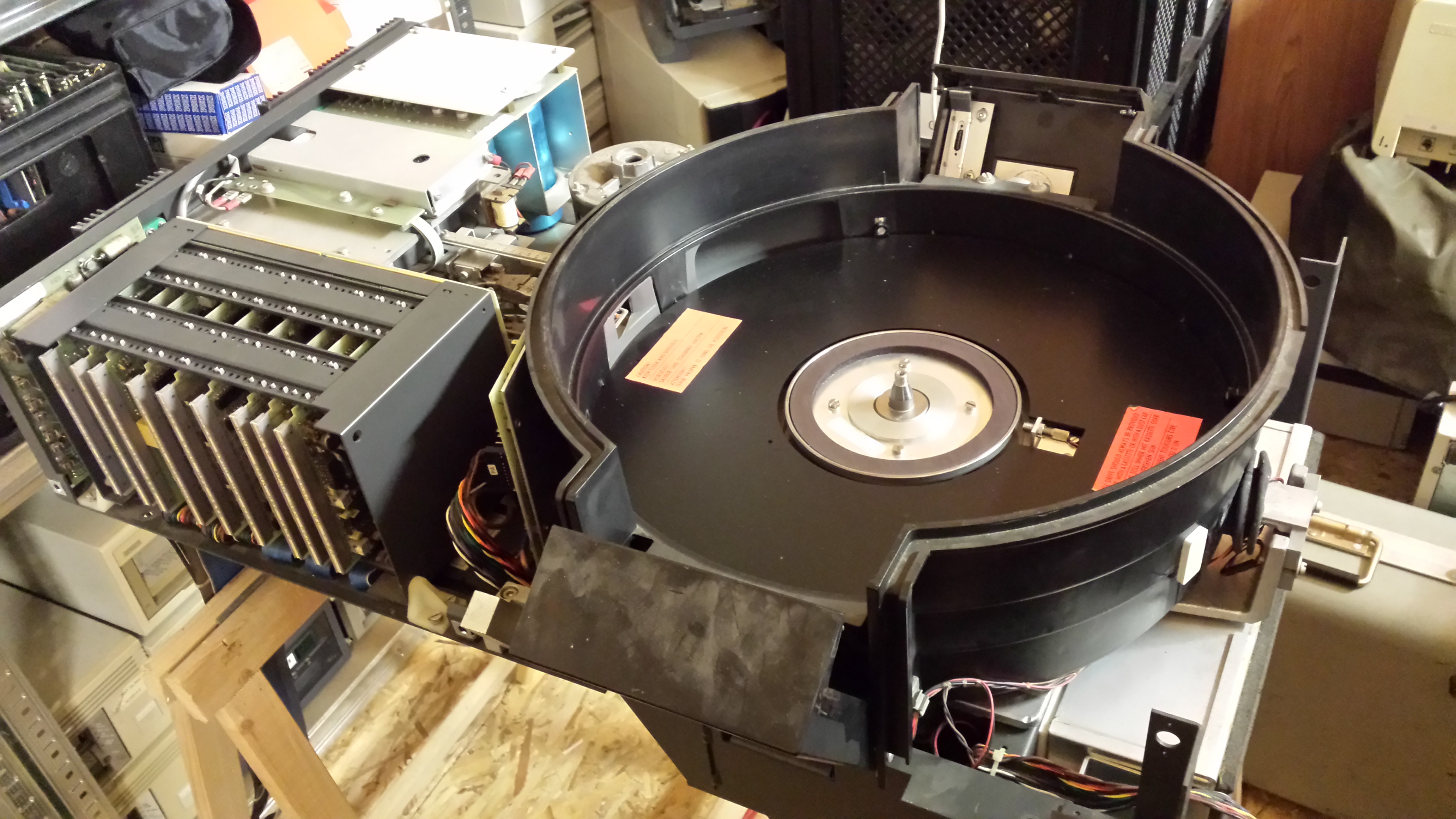
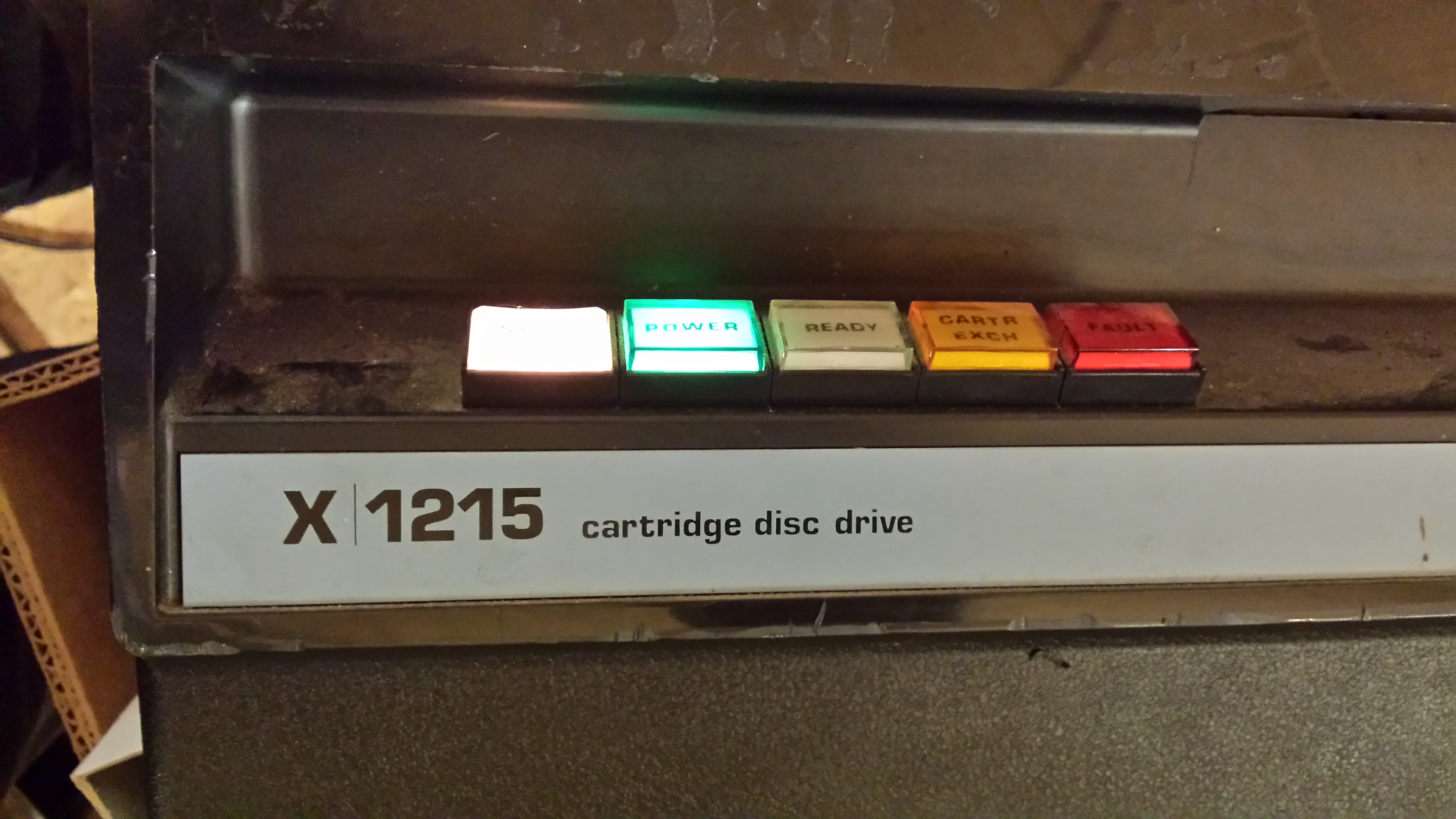
The Philips X1215 Cartridge Disc Drive stores a whopping 2.5 Megabytes on its internal fixed disk, and another 2.5 Megabytes on a removable disk in a cartridge. The drive takes 40 kilograms and 1200 watts of power to do so!
I've got two projects I'm working on involving the X1215; I want to emulate an X1215 CDD so I can boot disk-based operating systems on the P800-family systems in my collection, but I also want to get one of the X1215 drives back in working order, and build an interface so that I can make images of all the disk cartridges I have.
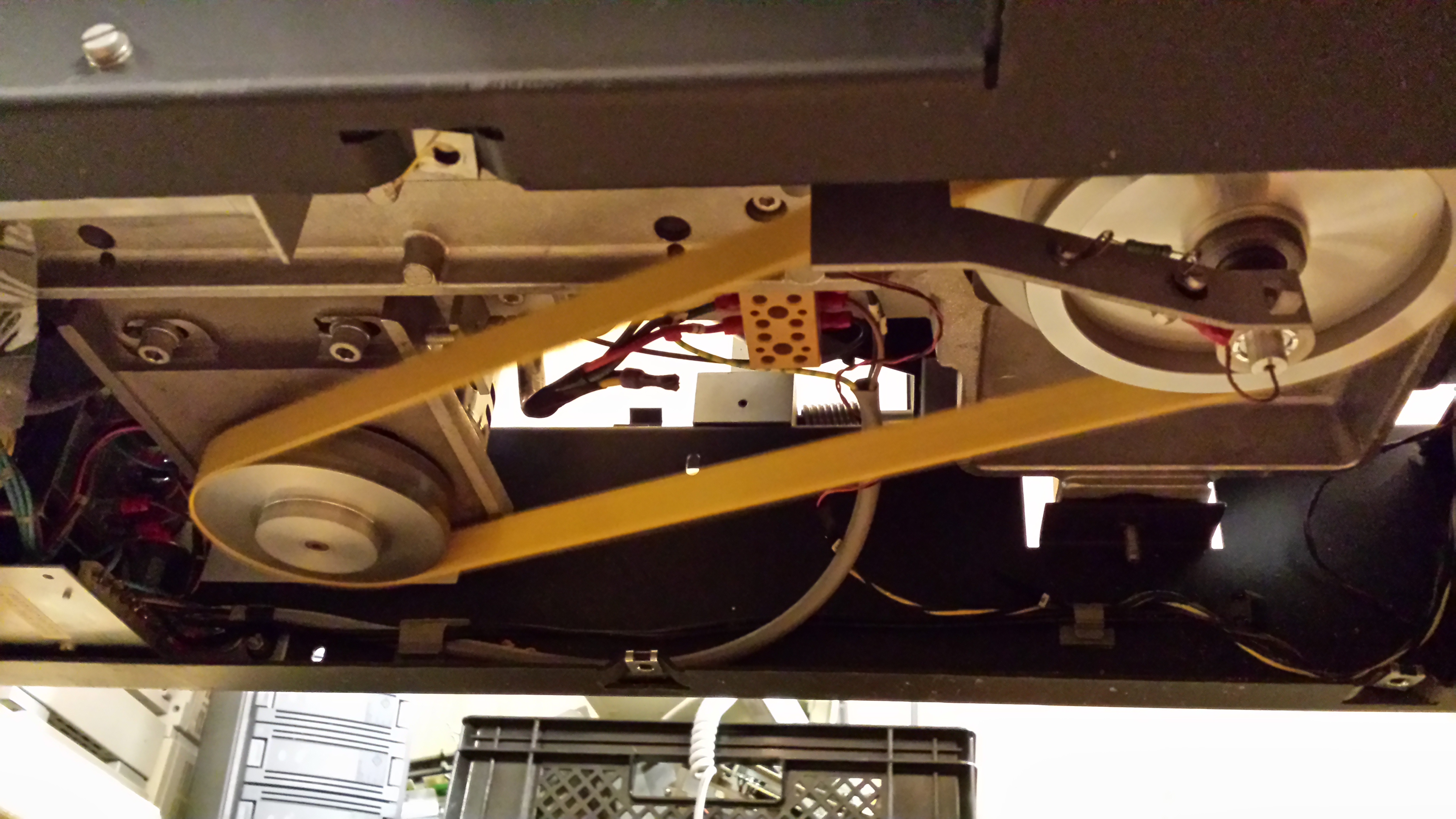
To this end, I cleaned the disk compartment, the heads, and the fixed disk (vacuum cleaner, brush, IPA swipes, gloves...), replaced the absolute filter, and replaced the drive belt.
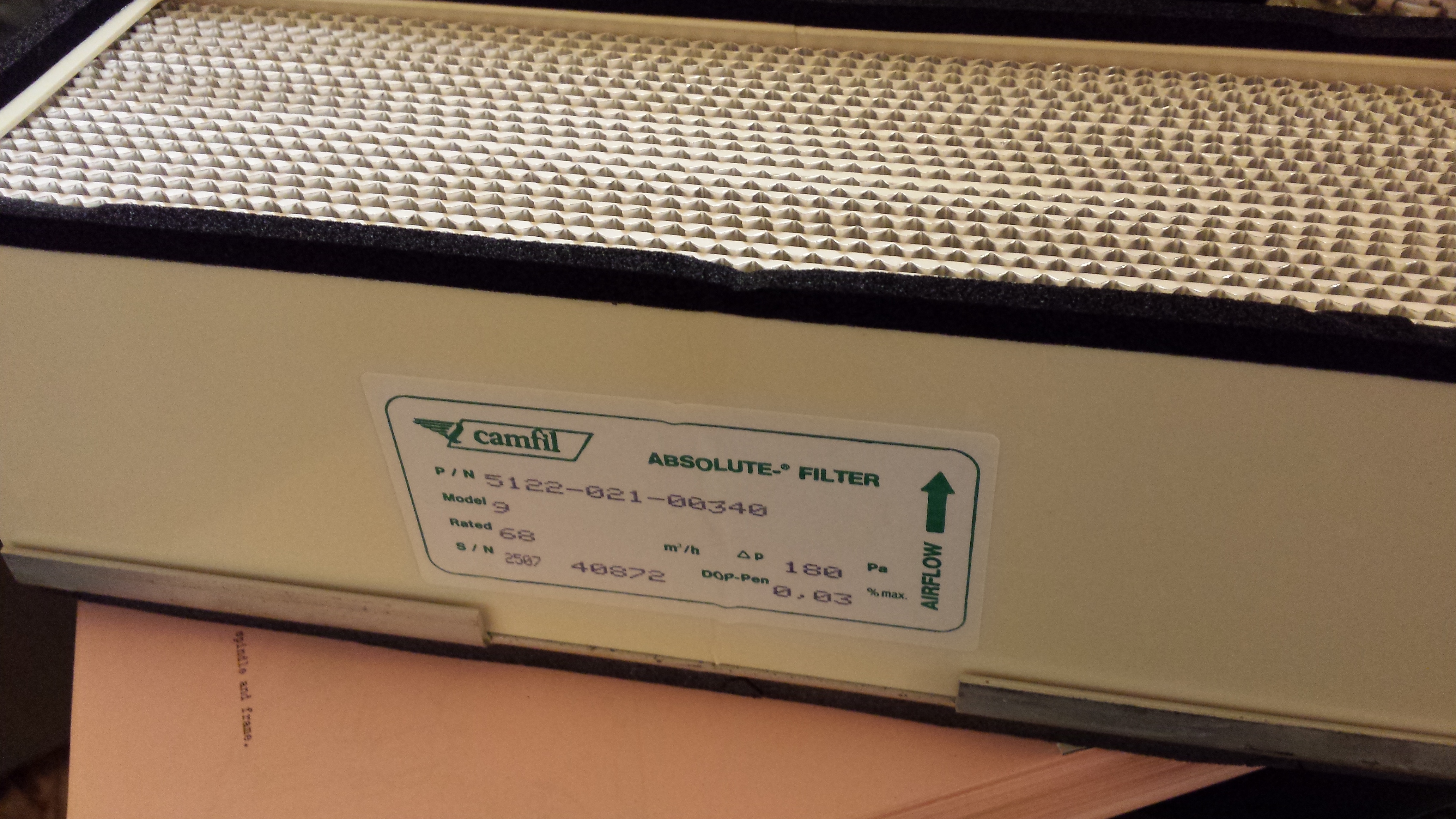
Having a few boxes full of original spare parts is always a good thing!
After these replacements, the drive is now subjected to the after-headcrash procedure, which consists of removing two fuses (so the voice coil won't be activated and load the heads), then letting the disk spin for two hours to get rid of any remaining dust.
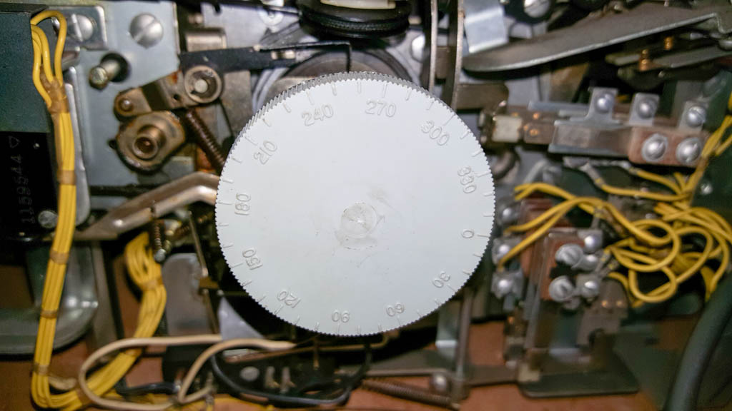
I can confirm that the disk is spinning at the proper 2400 rpm (by observing the index pulses with an oscilloscope), and after cleaning all the dust away and putting those fuses back in, the drive will now load the heads onto the disk without getting a head crash. The next thing to do is use the oscilloscope in various places to perform calibrations. Unfortunately, I don't have the calibration disk packs or drive tester that was normally used to do this, so I'll have to be a bit creative, and I may not be able to perform all calibrations. I'll just be happy if I can get close enough tocreate images of the cartridges I have. There's no telling what's on most of them until I can read them, so I hope I'll find something useful.
- Details
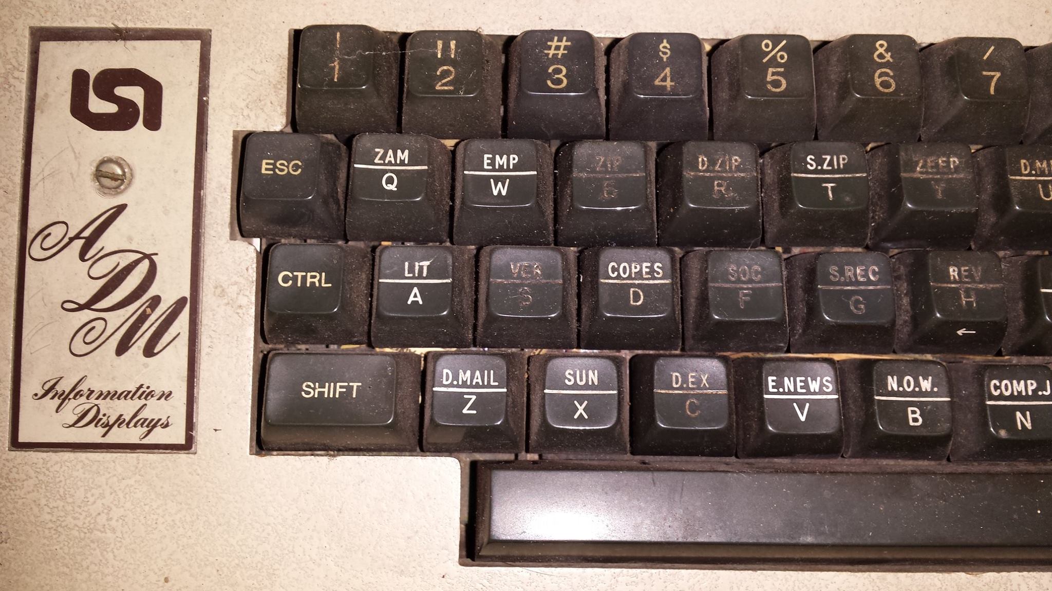
Needed something relaxing and rewarding to do for a couple of hours...
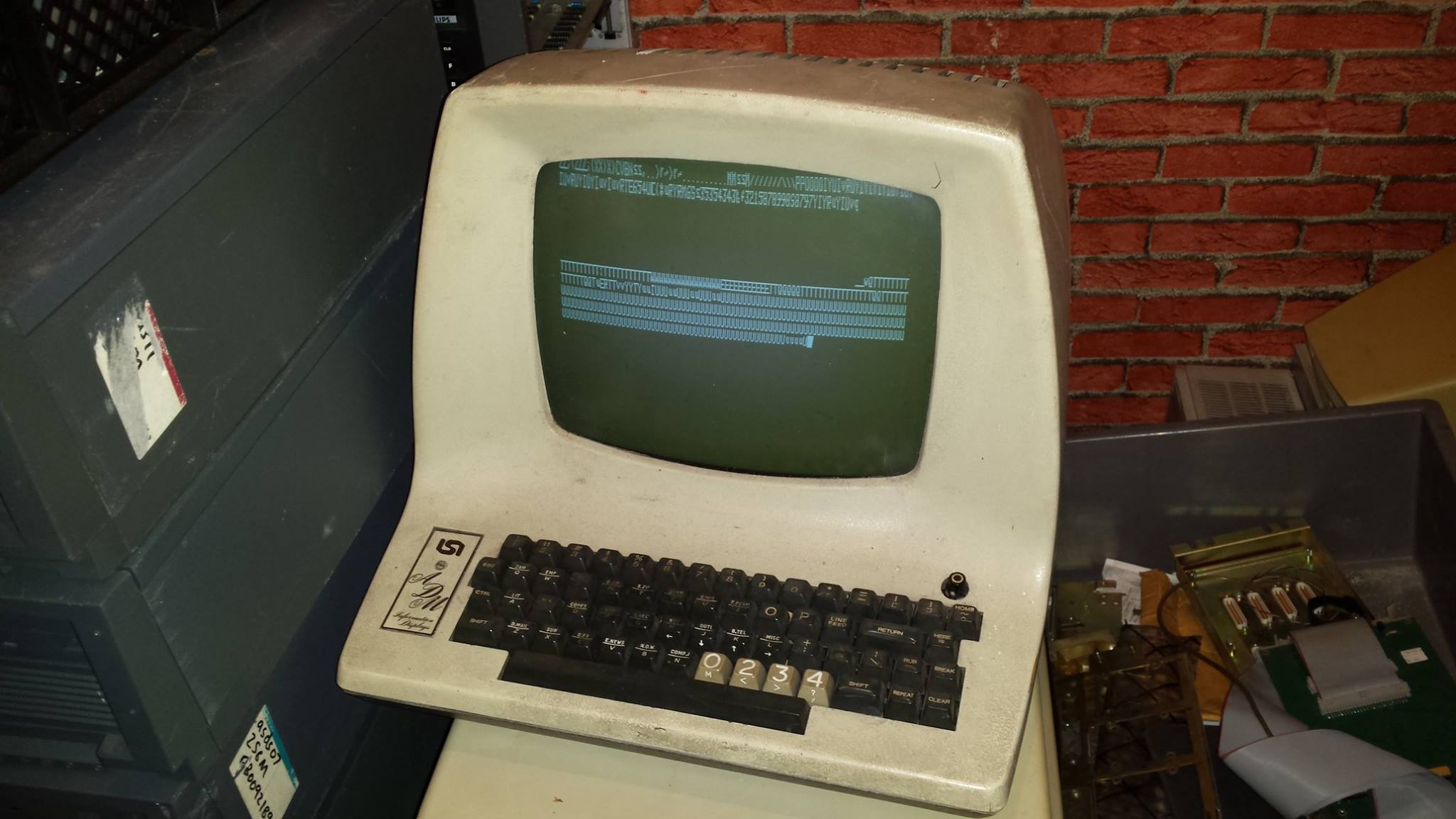
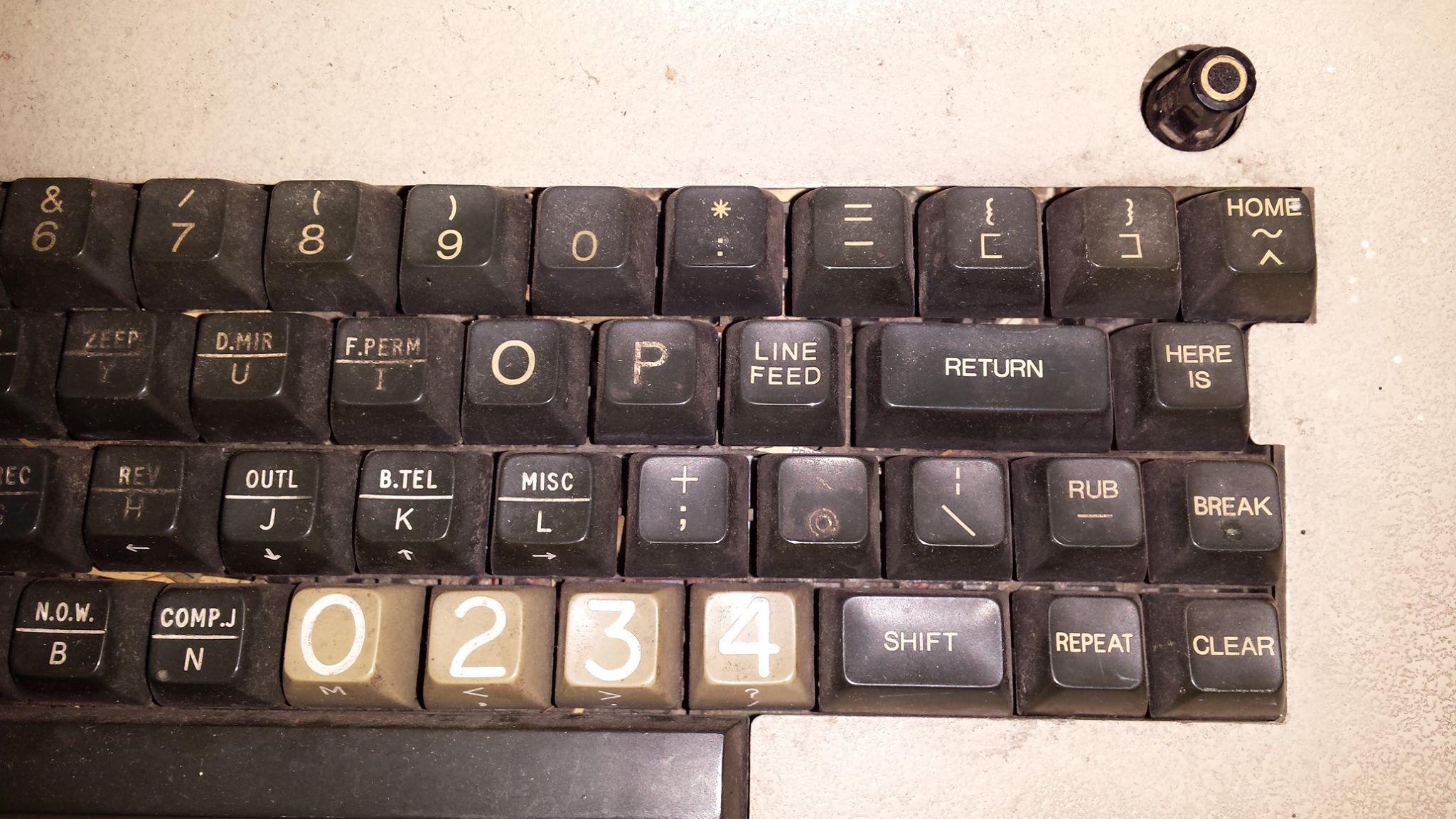
Decided to try to repair my ADM-3A terminal and succeeded. I had to replace the power cord (cut), then I also replaced some large capacitors as a precaution. Powered it on, then started troubleshooting with the maintenance manual (http://bitsavers.informatik.uni-stuttgart.de/pdf/learSiegler/ADM3A_Maint.pdf) in hand. One of the best maintenance manuals I have ever seen. Detailed schematics, with a full explanation of each circuit! Ended up replacing a 74LS32, 74LS161 and a 74LS74. Next job, obviously, is cleaning the case and the keyboard. The keyboard has some interesting keys, like "D.MAIL", "SUN", "E.NEWS", "COMP.J", "COPES", "ZEEP". It'd be interesting to find out what this terminal was originally used for...
- Details
I had a bit of a memory problem with the Nova 4.
The VC (Virtual Console) works okay when you hit the reset button, but when the computer is powered on I do not get the
OK
!000000
!
indication that indicates successful self-test completion. Instead, I only get
O
The VC does not respond at that point. Once I hit the reset button, I do get
O000000
!
But the K is still missing. The VC then responds as expected.
If I remove the memory board, the behavior is exactly the same, except that every memory address reads back as 177777 of course.
Accumulators with and without memory board:
- without - 177777 125252 076000 000701
- with - 127252 125252 076041 000701
This lead me to suspect that the memory at word 41 was incorrect.
Memory locations 0 - 40 were 052525, 41, 45, 51 were 127252, 42 and up (except those with the lowest bits being 01) were 125252.
So, it looks like the entire memory is written with 125252 (1010101010101010) first, then each word is first read, then written with 052525 (0101010101010101).
Sure enough, when I wrote 125252 to word 41, it looked fine, but when I wrote 052525 to word 1, it changed word 41 to 127252!
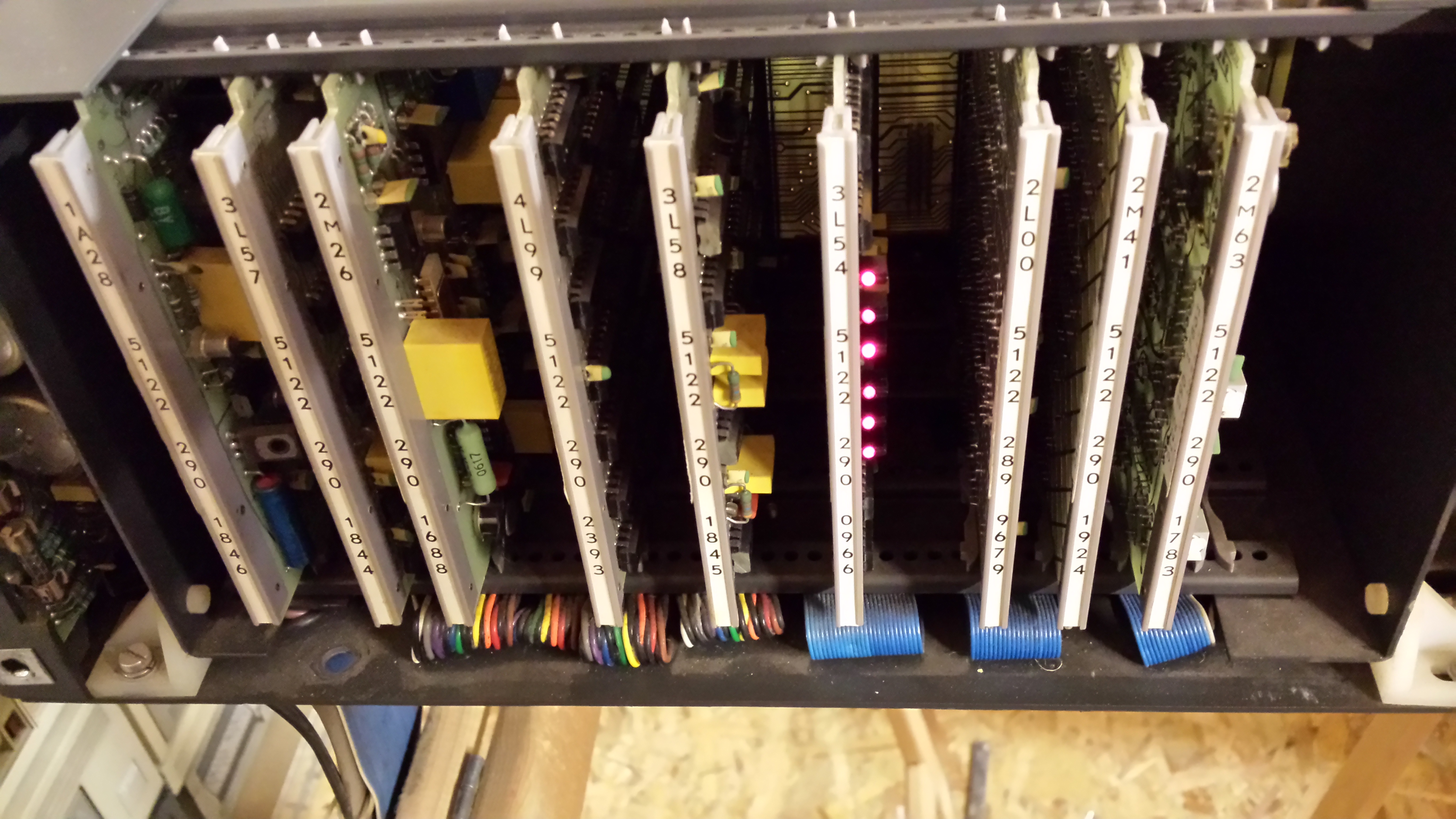
So, it looks like the memory chip that controls bit 10 for addresses ending in 01 (binary) is at fault here. I did some wire tracing, and came up with the following picture of the board
 +-----------------------------------------------------------+
 |          15  14              bit                   1   0  |
 |         +u+ +u+ ................................. +u+ +u+ |
 |         | | | |                                   | | | | |
 | 0xxxx00 | | | |                                   | | | | |
 |         +-+ +-+                                   +-+ +-+ |
 |                                                           |
 |         +u+ +u+                                   +u+ +u+ |
 |         | | | |                                   | | | | |
 | 1xxxx00 | | | |                                   | | | | |
 |         +-+ +-+                                   +-+ +-+ |
 |                                                           |
 |         :                                               : |
 |         :                                               : |
 | word    :                                               : |
 |         :                                               : |
 |         :                                               : |
 |                                                           |
 |         +u+ +u+                                   +u+ +u+ |
 |         | | | |                                   | | | | |
 | 0xxxx11 | | | |                                   | | | | |
 |         +-+ +-+                                   +-+ +-+ |
 |                                                           |
 |         +u+ +u+                                   +u+ +u+ |
 |         | | | |                                   | | | | |
 | 1xxxx11 | | | |                                   | | | | |
 |         +-+ +-+ ................................. +-+ +-+ |
 |                                                           |
 |                                                           |
 |                                                           |
 +-+                         +---+                         +-+
   +-------------------------+   +-------------------------+
So at least I can now trace an error bit to a chip. However, I must have damaged something in the process (believe me, I've been careful), because for all addresses ending in xxxx10, the data reads back as 000000 now. I hooked up my logic analyzer, and found that data is written to the memory chips in this row correctly. The data read from these chips is also correct. The data is then fed to a few 74153 4-to-1 MUXes. I checked the selection inputs to the MUXes, and these are wrong for row 2. The input for this comes from a 74S38 (which generates the two select lines to the MUXes). My suspicion is that the '38 was marginal to begin with. I Replaced this, then found 3 RAM chips that were bad. Replaced those too, and I now get the full
OK
!000000
!
On startup.
- Details
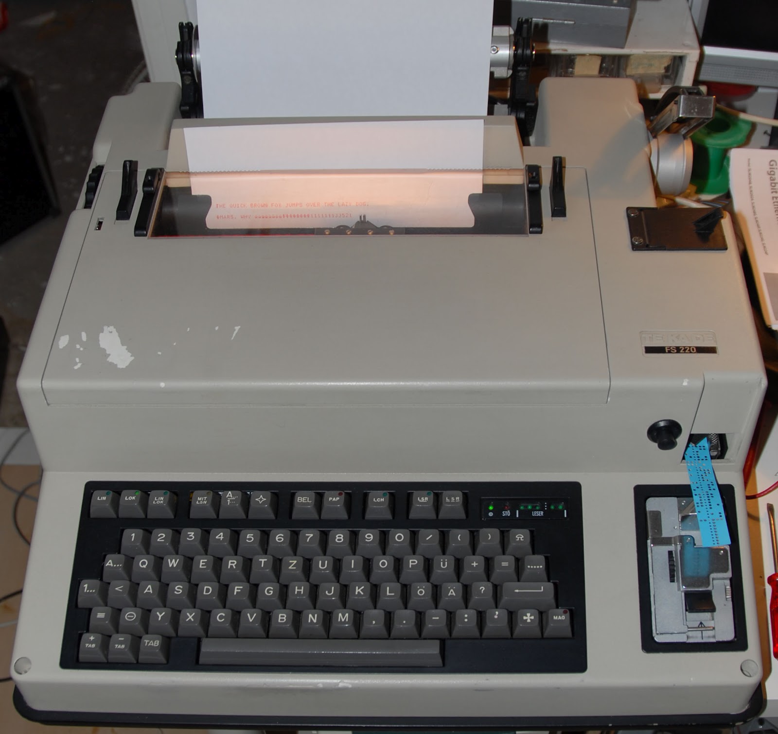
Today I did a little work on the console printer/keyboard to-be (a Tekade teleprinter used by the German armed forces). The power supply had a problem in the main 5v regulator. This consists of two LM317's in series with an op-amp driven feedback loop. I found out that both LM317's and the op-amp were broken (culprits shown right); possibly an over-current issue. I replaced those parts, and got the juice running again.
The teleprinter is running again (at least, in local mode). To connect it to the pc, I'll either need to build an RS232 to current loop converter, or try to find the V.10 interface card that was an option on these machines.
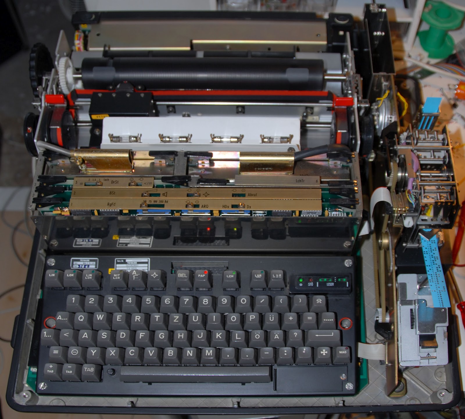
On the inside, these machines are a pleasure to work with. All functional units (power supply, keyboard, printer) can be removed by unscrewing 2-4 screws. The electronics are contained in a card-cage (three intel 8749 microcontrollers, CMOS logic, and high power transistors to drive the mechanical parts).
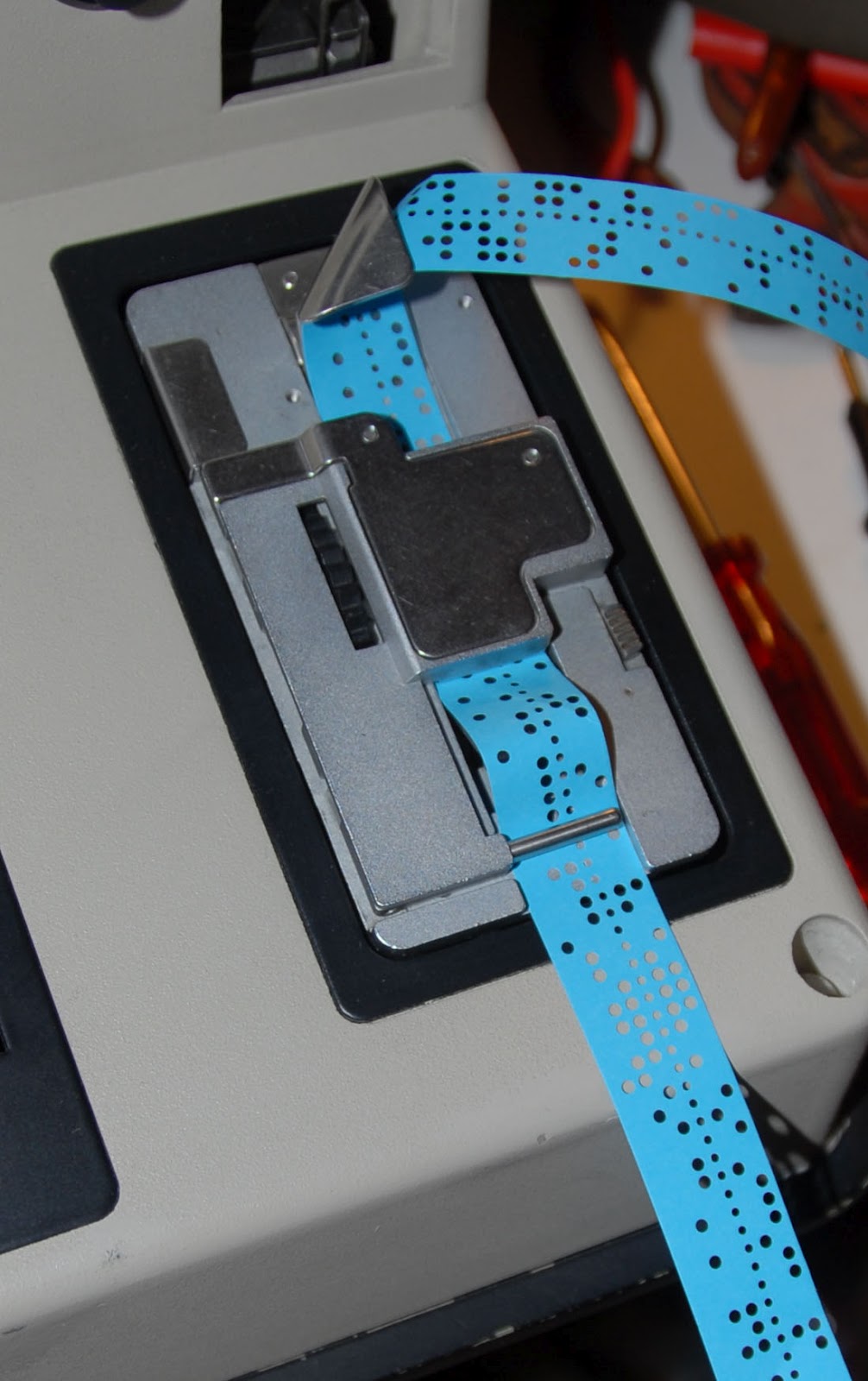
Functionally, it's equivalent to a Teletype ASR, with a paper tape punch and reader (except that these are 5-bit baudot code, not 7 or 8 bit ASCII):
- Details