
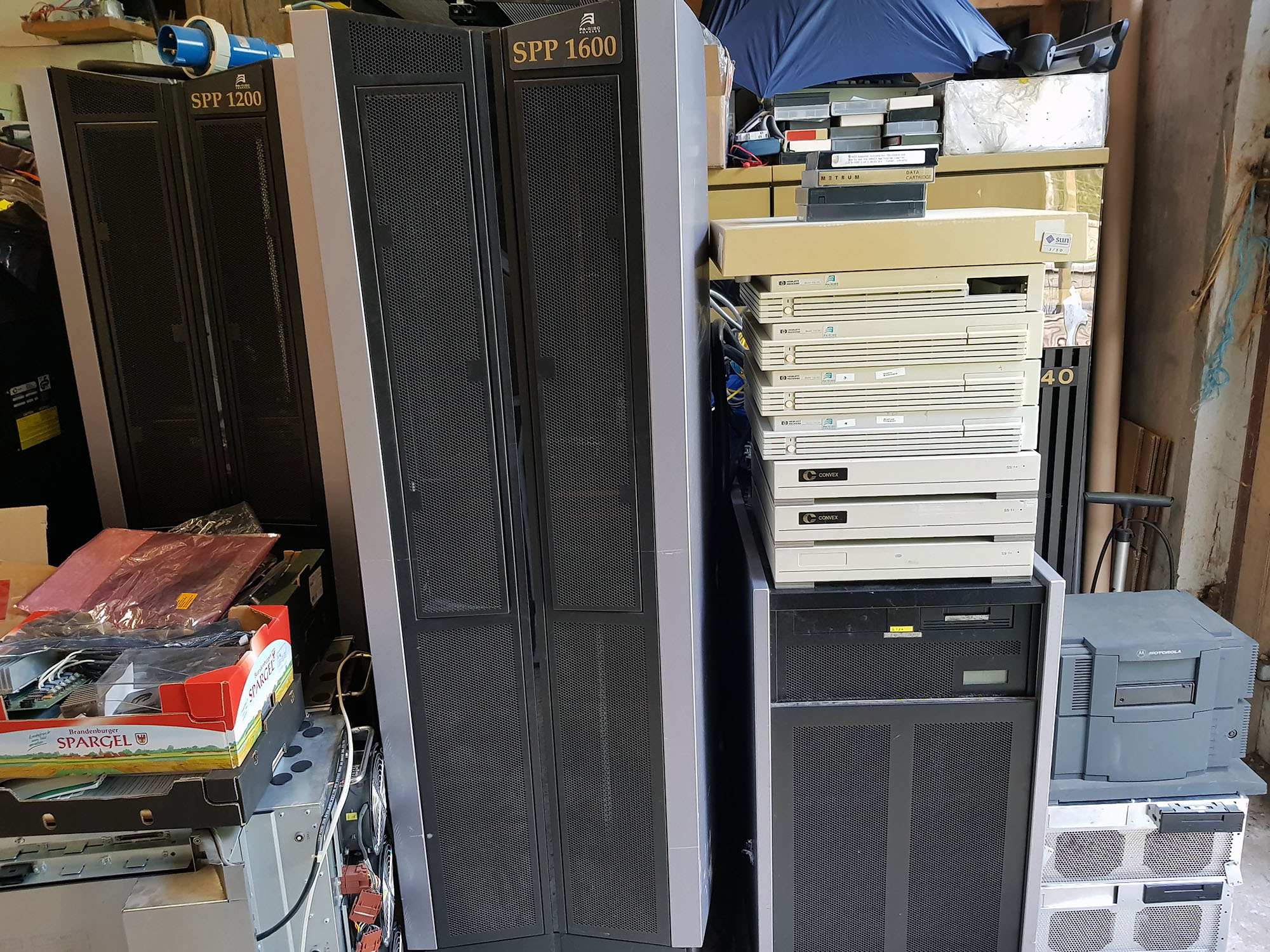
On Friday, the 11th of May 2018, my friend Andreas drove over from eastern Germany to deliver some Convex SPP supercomputers for the Convex Computer Collection.
The systems he delivered included a Convex Exemplar SPP-1200/XA, a Convex Exemplar SPP-1600/XA, a Convex Exemplar SPP-1200/CD, and a few pallets with spare parts and other bits and pieces, including four HP 9000 model 712/60's which were used as teststations for the Convex SPP's, a second SPP-1200/CD without skins, and a Convex Exemplar SPP-1600/CD without skins. There were also some unrelated bits, including four Sun SparcStation 1+'s which were used as test stations on Convex C3880's, a Sun 3/50 workstation, and a Motorola Series 900 system.
A first look


The SPP-1200's and SPP-1600's are very similar, the main difference being the cache size on the CPU's. The easiest way to describe the architecture, is to show you what's underneath those gray, textured metal skins. The smaller CD models ("Compact Design") open by releasing two latches at the back of the machine, and then flipping the outside of the case upward; the larger XA models ("Extended Architecture") have two curved side panels which are unlocked at the top of the machine and can then be taken off.
On the front of the machines one or two DAT drives can be found, as well as one (CD) or two (XA) alphanumeric LCD node status displays.
A special feature of the XA models are the row of green LEDs which occupies the center of the cabinet in the front, back and on top of the machine. This row of LEDs is entirely user-programmable, and is known as the MOD ("Meaningful Optical Display").


Inside, the same building blocks are used in both models. In the CD cabinet, an I/O chassis takes up the top part of the cabinet, and a node chassis takes up the bottom part. In the XA cabinet, the I/O chassis sits in the middle with node chassis both above and below it.
The cabling is visible on the right side of the cabinets. The I/O chassis is connected to the node(s) using SCSI cables, and the nodes are connected to each other using 8 big cables, which carry the CTI (Convex Toroidal Interconnect) Rings.
I/O Chassis

The I/O chassis contains up to 20 wide SCSI disks, and up to two DAT tape drives. There are two versions of the I/O chassis; one for single-ended SCSI disks, and one for differential SCSI disks. The disk controllers are all differential (this is high-voltage differential, not the more common low-voltage differential), and the single-ended I/O chassis uses six Ancot differential-to-single-ended converter boards. The differential I/O chassis uses a single converter board for the tape drive.
Node chassis


Each node consists of a backplane, which is populated with a number of large GaAs gate arrays which implement the 5-port crossbar switch. On the XA nodes, additional gate arrays are installed which implement the CTI interconnect which link multiple nodes together. So, the difference between the CD and the XA models is that the CD models consist of a single node, whereas the XA models can have up to 16 nodes (which requires 8 cabinets linked together).
On the right side of the backplane, up to 8 120MHz PA-7200 PA-RISC CPU modules (two per slice) plug in. These are the same CPU modules that are used in the HP 9000 J210 (XP-1200) and HP 9000 J210XA (XP-1600) workstations. On the left side of the backplane we find the MU (management unit) board, up to 4 memory boards (one per slice), one board with DC-DC power converters, and one I/O board at the top.
The I/O board offers space for 8 SBus (yes, the same SBus as used in Sun systems) cards. Here, we find disk controllers (SCSI) and network controllers (ethernet, FDDI, ATM).
Management Interface and Teststation

Whereas most other large machines of this era have a serial console port connected to a console terminal to control the operation of the system, there are no serial ports to be found on the SPP's. Instead, every node has a thin ethernet connector on the backplane, which is connected to the MU module. The MU module is a small computer built around a Motorola 68040 processor that controls the rest of the node in terms of initialization, diagnostics, and booting. All MU's in a system (one or more SPP nodes) are connected together through the ethernet bus (called the DaRT bus in Convex terms - Diagnostic and Remote Test), which in turn connects to a dedicated teststation (an HP 9000 model 712/60 workstation). All management of the SPP is done through a number of applications on this test station, one of which serves as the SPP's console terminal.