
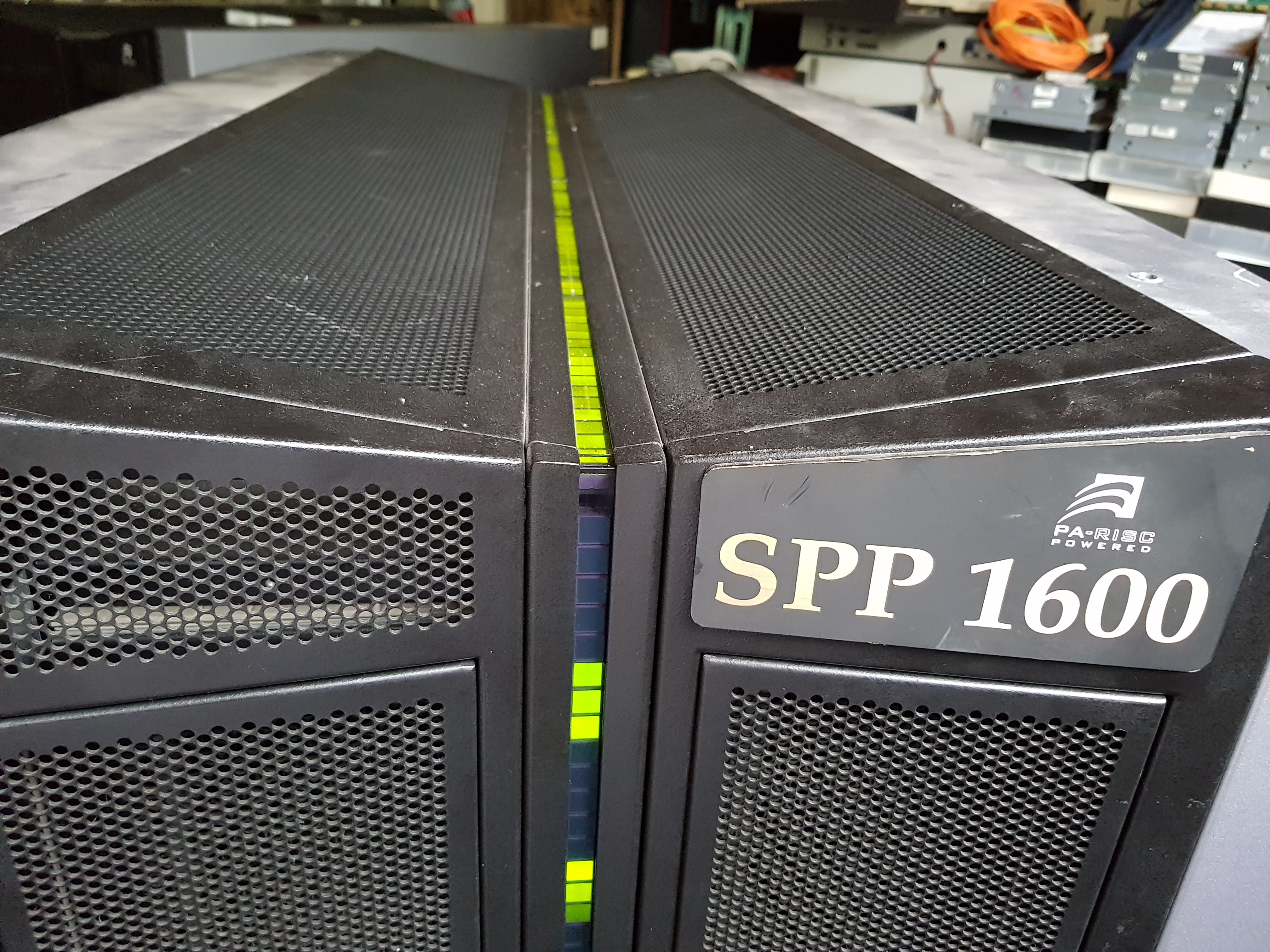
After the Arrival of the Convex SPP's, and after reading most of the hardware documentation that came with the systems, I worked mainly on the Convex Exemplar SPP-1600/XA for a couple of weekends.
Disk Backups

First, as always, I made backup images of the hard disks in both the test stations and the SPP’s themselves. In the SPP-1600/XA, these are wide, single-ended SCSI disks, which I can connect directly to a SCSI controller in a modern server; however, the disks in the Convex Exemplar SPP-1200/CD and Convex Exemplar SPP-1200/XA, as well as the disks in the spare disk cabinet, are wide, differential SCSI disks. Unfortunately, these are not the modern low-voltage differential (LVD), which my modern SCSI controllers can do easily, but the old-fashioned high-voltage differential, which requires a special controller (which are no longer being made, and therefore unavailable in PCIe. However, the disks in the SPP-1600/XA are single-ended, but the controller in that system is differential too. It turns out that the SPP-1600/XA disk cabinet contains 6 Ancot AS-SED-616M boards, which is a differential <—> single ended converter. This works perfectly for attaching single-ended disks to a differential controller (as in the SPP), but it works equally well for attaching these old differential disks to a modern LVD/SE controller. So, I ended up using one of those Ancot boards to create images of the differential hard disks.
When I worked on the Convex C220, I wrote a small utility to read and extract the files from the UFS filesystems on the Convex’ disks. I modified that utility a bit to handle the SPP’s partition table, and the slightly different HFS filesystem, and managed to do the same with all the SPP disks. That way, I could tell that I have four potential boot disks - one in each of the three complete systems, and one in one of the two spare disk chassis.

Of the four HP 9000 model 712/60 teststations, all four appear to be working, but one has a hard disk that no longer works. The other three boot fine. Two of these have the teststation software for the later SPP-2000 systems loaded, which is not suitable for use with my SPP’s, but the last of the four teststations has the SPP-1x00 software loaded.
So, the idea is that you connect the teststation to the node(s) DaRT (diagnostics and remote test) port(s) using a thin ethernet (10base2) cable, power on the SPP, and then get status messages and issue commands on the teststation. For this to work, the teststation and the DaRT ports need to be in the same subnet, and the teststation needs to know the DaRT’s IP addresses. As I found out much later, the teststation was set to a different subnet than the DaRT ports on my SPP’s, and for this reason it was not communicating with the nodes. I believed it was not communicating because the nodes were not initializing properly, so I didn’t think to check the network addresses. The following debugging might have happened a lot faster if I had known that the teststation can still communicate with the node even if the node doesn’t initialize properly.
Power Supply Debugging
None of the SPP systems I received powered on OK from the start, so it was time to do some debugging, starting with the SPP-1600/XA.
The first problem I found, is an error message on the LCD display for both nodes with
Node 0, SN 2010188
Node Power OFF:
Node Init FAILED
 Status 0000099a
MU Status code 99a translated into “WEAK 48V” according to the maintenance manual. Had I setup the connection with the test station correctly, a clearer wording of that error would have appeared there. The system has three 48V power supplies in the bottom of the system. The output from the three supplies is or-ed together, and then fed to the nodes and the I/O chassis, where DC-DC converters convert the 48V to the numerous voltages the system needs (+1.2V, +2V, +3.3V, +4.4V, +5V, +12V, -2V, -3.1V, -4.5V, -9V). In the CD cabinets, a single 48V supply directly feeds the entire system, but in the XA cabinets with it’s multiple 48V supplies, a small power controller board monitors the three supplies and relays information about the supplies to the nodes. One of these signals is called “NOTENOUGHPOWER” (active low), and it’s asserted when there are two nodes in the cabinet, but less than two power supplies are good.
In our case, all three supplies were good, but the NOTENOUGHPOWER was at 0V, so the nodes believed there was insufficient power to turn the system on. I found out that the reason the signal was at 0V was that the power controller board itself was not powered. It has a small DC-DC converter on it to turn the 48V from the power supplies to 5V for the logic on the power controller itself. The converted is protected by a small fuse, and that fuse was blown. After replacing that fuse, the status on the two LCD displays changed:
Node 0, SN 2010188
Node Power ON: F7FF
Node Init Complete
and
Node 1, SN 2010160
Node Power OFF:
Node Init FAILED
 Status 00000997
So, node 0 seems to be OK now, but node 1 still has power problems (997 translates to “supply missing”). I decided to continue debugging with just node 0, so I switched node 1 off internally.
Debugging node 0
Now that the node initialized completely, I figured I should be able to connect to the node from the teststation. I was puzzled about not getting a connection, until I sent a broadcast ping from the test station and got a reply indicating that the node was in a completely different subnet. I reconfigured networking on the teststation, and then got a connection with the system. When the teststation has a connection to the node, it opens two terminal windows; one is a diagnostic shell, and the other is a console on the SPP.
After the MU initializes, the SPP starts booting OBP (OpenBoot) firmware on one of the PA-RISC processors. That would normally bring up an OBP prompt on the console window, but instead I got a hard error, indicating an error with CPU #6. I swapped Cpu’s 6 and 7, and still got the hard error on CPU #6. I then took CPU 6 out, and let the MU know that CPU 6 was no longer there to keep it form complaining. Any time you change hardware, you need to use ccmu (Convex Configuration Management Utility) to let the MU know what hardware to expect. Typically, you type “ccmu” to enter the utility, then “pull” to transfer configuration data from the EEPROM to RAM on the MU, “up” to upload the data from the MU to the teststation, “get AVAIL_HW” to display the currently configured hardware (one bit per component, 1=installed, 0=not installed), “set AVAIL_HW 0x80ff1fff” (just an example, this one would indicate everything is installed), then “auto” to automatically determine the other variable values, and finally “down” to copy the data back to the MU’s RAM, and “push” to store it in the EEPROM.
After removing CPU 6, the hard error was gone, and I got the OBP prompt. Happy with that for now, I tried booting from the system disk, which ended quickly with lots of errors from the disk. I wrote the image I had made of this disk to another, good disk, and replaced the failed disk with that one. Now the system happily boots SPP-UX version 5.3 on 7 of its CPU’s.
Lessons learned
With that, the first weekend had come, and the first weekend had gone. Time to recapitulate what I learned so far:
- The most important thing I've learned is that even when the front panel says "power off - node init failed", the teststation can still talk to the MU board in most cases, as long as the IP addresses are set up correctly (for which you can use the node_ip_set command). So rather that troubleshooting power supply problems in the blind, you can turn bits and pieces of from the teststation (using pce_util) and see what happens. pce_util is smart enough that it won't let you turn on power supplies that should not be on when other supplies are still off. Unfortunately, it is not smart enough to tell you what power supply keeps the node from initializing properly, but you can manually turn the system on a few power supplies at a time, until you hit the one that fails.
- The second thing I learned is that if you want to run a node with less than all 4 slices (useful for debugging), you need to tell the MU what hardware is present through the ccmu utility. Failure to do so will cause the MU to try to turn on power supplies that aren't there, and complain about them.
- The third thing is that it's easier to bring up single nodes first, debug those, make sure each of them can boot the OS, and only then try to connect them as a multi-node system.
Getting the last CPU working on node 0
The second weekend, I set out to work on the SPP-1600/XA again. I had this one running on a single node (node 0), with 7 out of 8 CPU's. Replacing the CPU had not fixed the CPU hard errors, but I had not yet run CST on this node.
Once you have any power supply problems sorted out, CST (Convex Scan Test) is your friend for checking board connectivity as well as gate array sanity. It uses a JTAG interface on all the gate arrays and on many other components (there are 352 components in 5 scan rings that get tested), to load lots of different known input states into these components, then checks the output state for correctness. It also verifies that components are connected correctly by setting up a known output state on one component, and checking the input state on the components it connects to. It does this for static signals (“DC Connectivity”), but also verifies that the behavior is correct at high speed (“AC Connectivity”).
So, I ran CST, and it flagged several paths as faulty in the DC connectivity tests. I cleaned all of the board-backplane connectors with 99% isopropyl alcohol, which took the number of faulty paths down a bit, but not to 0. One of the suggestions in the service manual on connectivity errors is to check the torque on the screws holding the gate-arrays (GA’s) in place on the backplane. So, I checked, and most were well below the 7 lbs/in recommended, do I properly fixed all screws holding the GA's down, and that took care of the remaining DC connectivity errors. However, the APA3 gate array (Avalon Processor Agent for slice 3) was flagged as faulty. Fortunately, I do have a box with several spare gate arrays (some still in their original packaging) as well as a box of brand new CIN::APSE LGA sockets, and there was a spare D-revision APA. Attached to the inside of each system cabinet is a plastic bag with two small rods with threaded ends. Now I learned what those were for!


Each gate array is fixed to the board with four philips screws. On the backplane, and on the underside of the GA is just a grid of gold-plated copper dots (LGA - land grid array). Between the backplane and the GA, a Cinch CIN::APSE socket is placed; this is a thin plastic wafer, with a hole in it for each pin. In each hole sits a tiny cylinder made of very thin gold-plated beryllium wire, spun like cotton-candy. On top of the GA sits a heatsink, with a thin thermal conduction layer in between. This sandwich of socket-GA-thermal compound-heatsink is all held in place by these four screws. The secret to replacing a gate array whilst keeping everything aligned properly, are those two small rods.
First, you remove two of the screws, from opposing corners of the GA. You then put the rods into those two holes, and screw the rods into the backplane. You can then take the other two screws out, with the rods keeping the old assembly in place. You can then carefully slide the old assembly off the board. You then clean the pads on the board with isopropyl alcohol, and carefully slide a new socket onto the rods, and in place on the backplane, ensuring that the guideposts on the socket slide into the corresponding holes on the backplane. You then slide the GA, thermal compound, and heatsink on, and put the first two screws in. Then you take the rods out, and put the last two screws in.
So, I replaced the faulty gate array and its socket, after which all tests passed, and I could boot SPP/UX on all 8 processors in node 0.
Debugging node 1
I then turned my attention to node 1; its MU initialization failed with an error code 997 (no supply). Using pce_util to turn supplies on one at a time, it was revealed that the VDD_GA supply had failed, so I replaced one of the DC-DC converters on the backplane.

The MU then failed with an error code 996 (shutdown abort). Again using pce_util, I could narrow it down to the VDL supply. I replaced it, but still the same error. I then put the original DC-DC converter in a small test bench I built, and verified that it was delivering the +3.3V as needed. This problem turned out to be a short-circuit on the MU board. I replaced the MU board, and now the node initializes. However, on this node, even after cleaning all contacts and re-torqueing the GA's, there were lots of connectivity errors on this node, and one of the scan rings was broken.
To make a long story short (I won't replicate 7 pages of troubleshooting notes from my notebook), the memory carrier board in slice 2 turned out to be broken, one CPU was bad, and I had to replace the CCMC2 gate array in slice 0. Anyway, I ended up with a node 1 (temporarily re-assigned as node 0) which could boot SPP/UX on all 8 of its CPU's.
Sweet Sixteen


Finally, I re-assigned node 1 to be node 1 again, fired up both nodes, and ran the verify_cables test. That test flagged a problem in ring 2, and it turns out that the cables were reversed on that ring (input connected to input, output connected to output). Fixed that, and now the two-node system is fully operational, running SPP/UX version 5.3 on all 16 CPU's.