
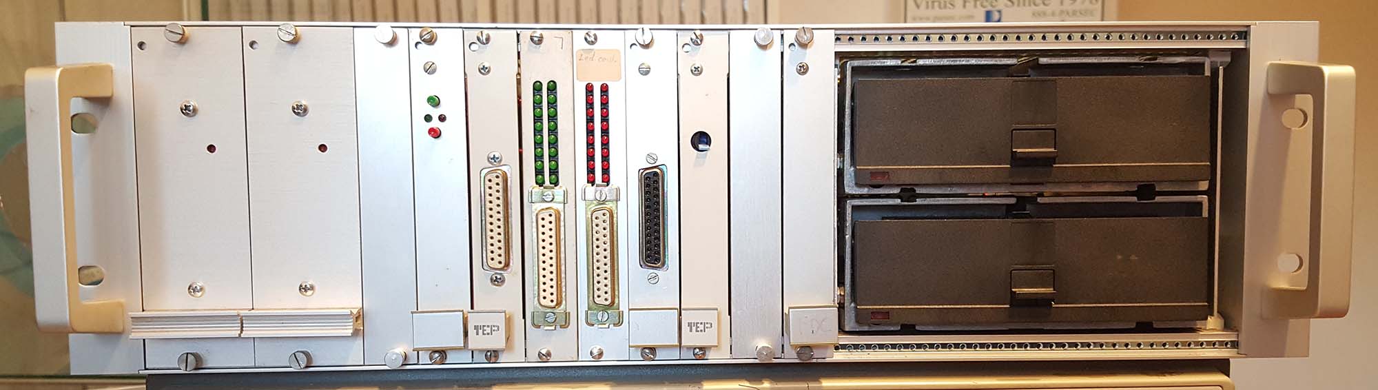
This TEP FTI990 initially seemed to be in good shape, however, initially I couldn't get it to boot. In the end several problems were found that conspired to prevent it from booting.
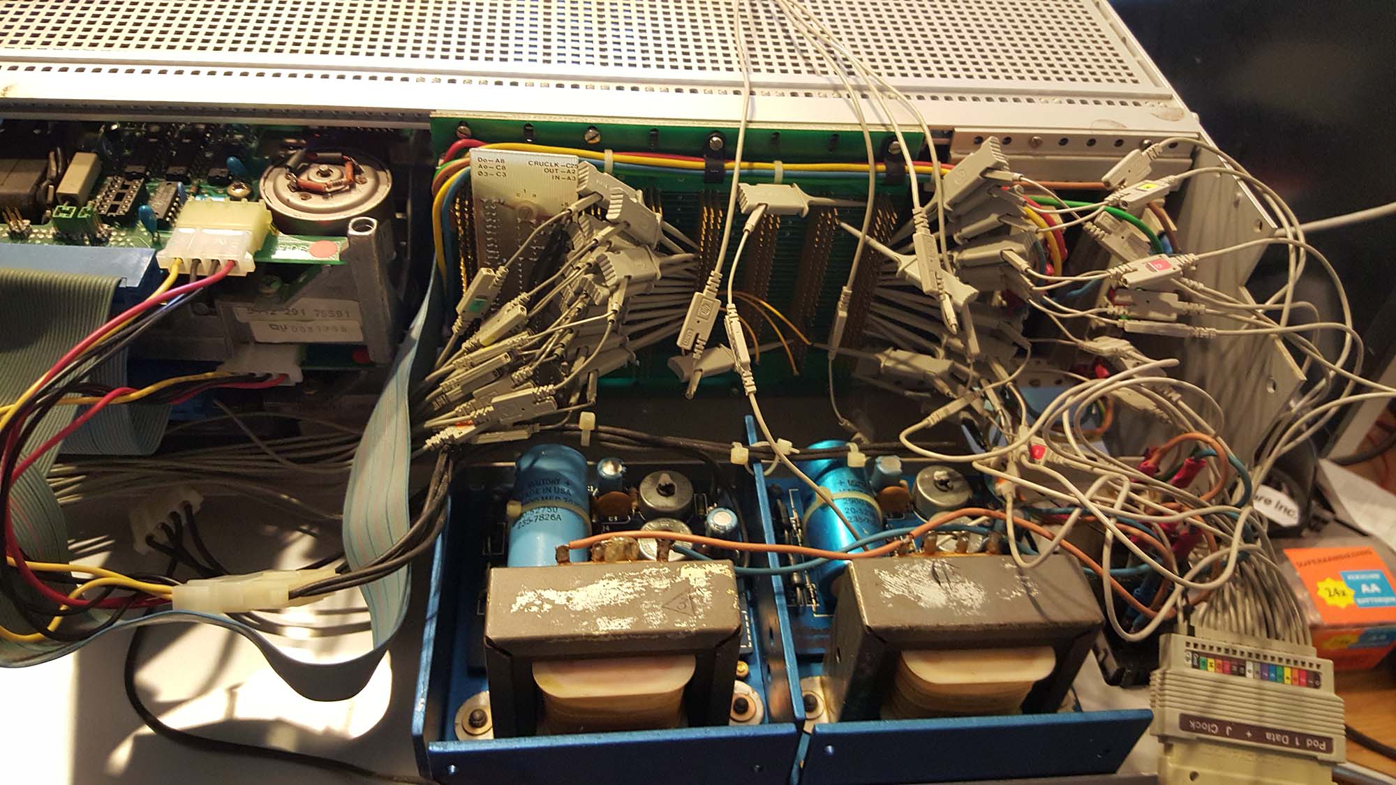
Most problems were identified by hooking the system up to a logic analyzer (my trusty HP 1660C), then following the execution of code through the ROM-based boot loader. For this, I dumped the EPROMs' contents to a file using an EPROM programmer, then hand-disassembled the relevant bits of code.
 The first problem was that the CPU was not running - at all. It requires -5V; this voltage is derived from -12V by a 7905 regulator, located on a terminator card in the back of the machine. Replacing the 7905 fixed this porblem.
The second problem was that two of the data lines were stuck together; this was due to two of the wire-wrap pins on the backplane touching each other. After this problem was solved, the system could execute the first few instructions in the bootloader.
The next problem was more serious; most RAM locations read back as FFFF, even after being written to. Since the TMS9900 uses RAM to store it's registers, this leads to a very quick blow-up. The cause became apparent after hooking some extra wires from the logic analyzer up to the chip-select lines of the EPROM and RAM chips. it turned out that six of the eight RAM chips were never getting selected, even when they should be. After a little digging the culprit turned out to be a MCM7649 4kbit PROM that drives the chip select lines; it looks like its output buffers got blown. After figuring out what the memory map should look like, I rigged a replacement with a couple of 74LS00's
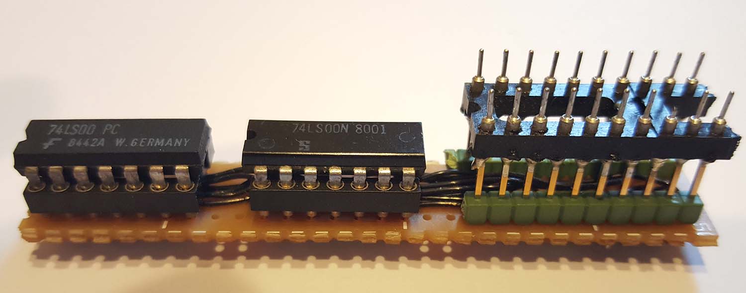
Address decoder PROM replacement
The address decoder provides the following mappings:
0000 - 3FFF  1st pair of RAM chips
4000 - 7FFF  2nd pair of RAM chips
8000 - BFFF 3rd pair of RAM chips
C000 - DFFF 4th pair of RAM chips
E000 - EFFF hole for memory mapped I/O devices (noteably the floppy disk controller)
F000 - FFFF pair of EPROMs
This circuit worked like a charm. After identifying and replacing a bad RAM chip (one data bit stuck at 0 on reading), I got to the point where the system started addressing the serial port on the CRU card. Unfortunately, the CRU card had its DIP switches set to the wrong address, but that was found and fixed easily. Figuring out the correct terminal settings took a while, but with some help from the listings, I figured out that it should be 7 data bits, even parity, 2 stop bits at 110, 300, 1200, 2400, 4800, 9600 or 19200 baud. After hitting the reset button, you're supposed to send a <CR> to the port to autobaud it.
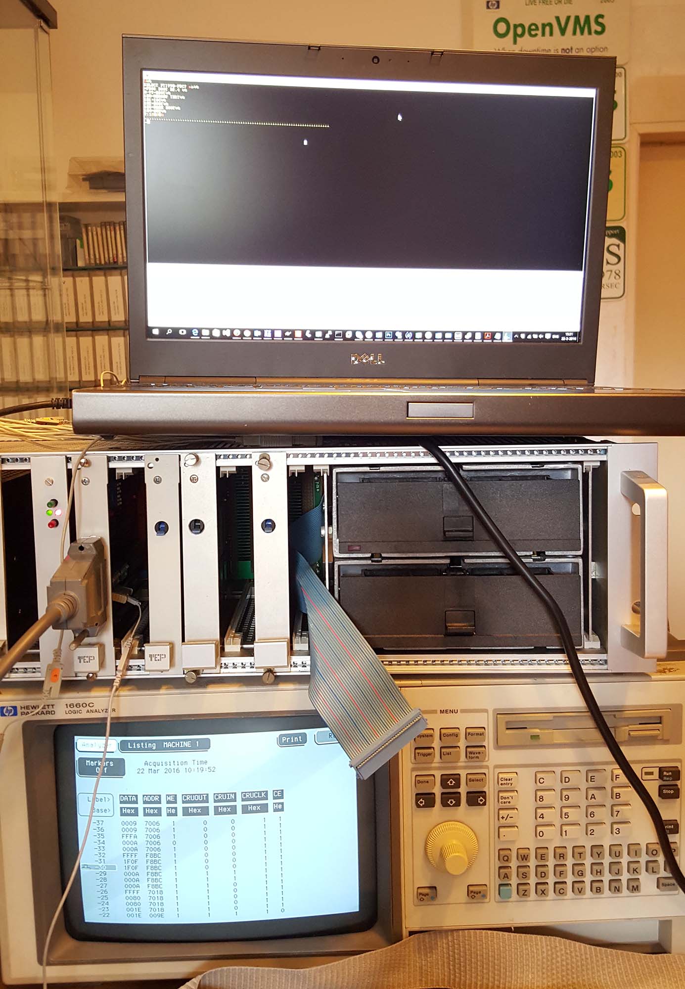
Talking to the serial port for the first time
Once the serial port was configured correctly, I got the PDOS boot menu (all part of the EPROM bootloader). Memory test was successful, but the boot command didn't do anything. Eventually, I found out that the floppy disk controller was listening to the wrong address. After fixing that, the floppy drive lights up at boot, but nothing else happened. I found out that the floppy cable wasn't terminated properly, and that the floppy drives needed some lubrication.
But, in the end, I finally managed to boot and run the PDOS operating system from a 5-1/4" floppy!