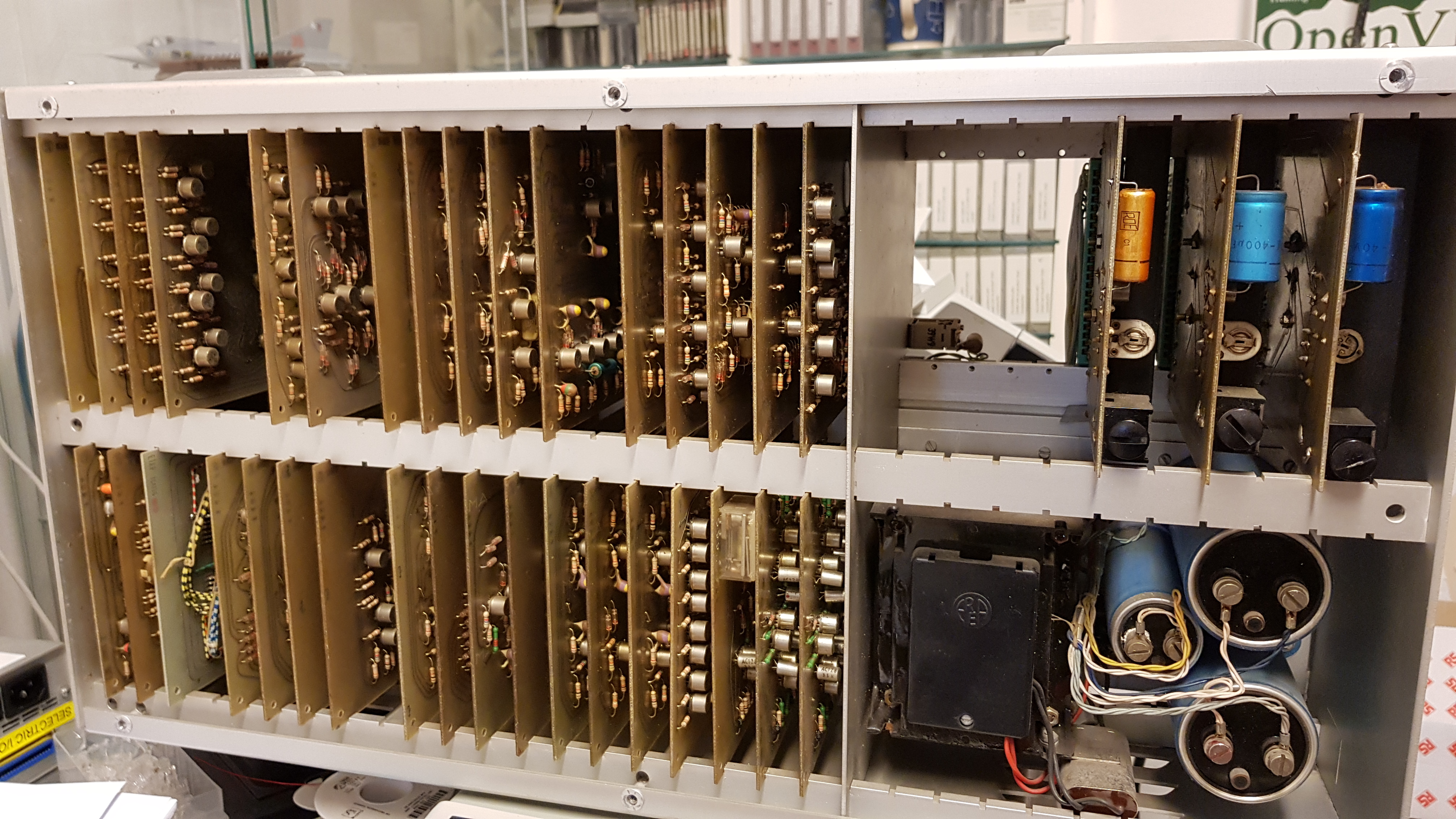
So, here's a bit of a mystery I'd like to share with you: I recently received this mystery device from Germany, and I have no idea yet what it is.
It's an aluminium box, 58 centimeters wide, 31 centimeters high, and 20 centimeters deep, with ventilation holes on the front, back, top and bottom sides. It sits on four rubber shock-mounts. The only features on the outside are a power cord, two 60-pin connectors (more on those later), a stamped logo "ETAP" and a type plate that reads "Serie No 1404 / Model 1-31 / 220V ~ +/- 10% / Freq. 50-60 Hz"
Opening it up reveals a neatly laid-out interior with power supplies on the right, and 34 circuit boards on the left. Opening the back reveals very neat wire-wrapping.
The power supplies deliver regulated +6, -6 and -18 volts, as well as unregulated -24 and -36 volts. I had to replace the electrolytic capacitors for the power supplies to work reliably, and I had to replace one of the ASZ16 power transistors. The circuits are al built using discrete germanium diodes (OA91 and TF20) and germanium transistors (mostly 2N404, but also 2N1308, 2N1309, AC128, ASY74 and ASZ16). Date codes on the transistors are between 1966 and 1968, so we can date the device to the late 1960s with high probability.
All circuit boards are 155 x 125 mm in size, and have a 22-pin card-edge connector (some modules are double-sided and hav a 2 x 22 pin connector).
Logic levels appear to be 0 volts ("0") and -6 volts ("1"). Some of the boards contain 4 flip-flops with various combinations of edge-triggered and level-triggered set/reset and toggle inputs. Also present in the device is a bit of core memory; 4 planes, each consisting of 32 x 16 cores. The read amplifier for the core memory is a bit special, as it doesn't use discrete transistors, but instead uses a Philips/Mullard RA1 combi-element. These are pre-packaged logic modules (there's a PCB inside the yellow metal housing) that were used extensively in the control systems for the London Underground.
At first, I thought the device might have been made by the Belgian company ETAP, that was originally active in nautical electrical systems, and is now active in lighting. Clues that led me in this direction were the type-plate "Serie No", and the transformer, which was made by Erea, another Belgian company. I contacted ETAP, but one of their ex-employees assured me that they did not build this device.
The other clue as to its origins are possibly the connectors on the side. These turn out to have been made by LM Ericsson, and were used extensively in their telephone exchanges. A Swedish friend sent me photos of a couple of page from an old LME catalog, which clearly show the same connectors.
So, what does the device do? I don't know yet; I've drawn complete schematics of the device (see below) and spent some time analyzing them. However, the use of multiple astable multivibrators as clock sources for different parts of the circuit, the use of gated clocks, and the use of single-shots to delay and/or hold signals for a certain period make it more difficult to ascertain the timing of things, and hence to analyze the circuit. What I do know:
- Four inputs are almost fully decoded throughout the device, and each different combination of these inputs makes the device act in a different way. I'v come to think of this 4-bit input as the "opcode" for the device.
- Only a part of the core memory (12 x 31 x 4 bits) are used.
- The Y address to the core memory comes from a single 4-bit binary counter. If the counter's value is below 4, the core memory is inactive. The counter can count up or down.
- A 3-bit counter, located on board P10, which I've therefore taken to calling the "P10 counter" increments when the Y address rolls over from F to 0 (so only when the Y address counter is counting up).
- The X address to the core memory comes from a multiplexer, which can gate one of 4 addresses; two of these come from counters (one 6-bit counter and one 4-bit counter), and two of these are external inputs on the device. If the address is 3, or if the address is above 31, the core memory is inactive. Which address is gated depends on the opcode, the P10 counter, and whether or not certain bits are 0, among other things.
- Data read from the core memory is stored in a 4-bit register, which can also act as a counter. Under certain circumstances, one of 9 inputs causes a value between 1 and 9 to be added to the register, which rolls over when it reaches 9. The inputs can also cause 10 minus the associated value to be added, which adds the associated value. There also seems to be logic to carry a roll-over to the next digit. The contents from this register may be written back to the core memory (or written to the core memory in a different location), and they may be used to select one of 10 outputs on the device.
- Curiously, adding a value X to the data register may also add that value X, or 10 times that value X to one of the two X address counters.
- Overall, the device seems capable of storing 31 12-digit decimal numbers, and adding and subtracting values to these numbers.


