
I have resumed work on the FPGA implementation of the IBM 360/65. I now have access to a complete set of IBM ALD's for the 7201-02 (the FAA 9020 customized version of the 2065 CPU), and because of that, I've decided to change how I'm implementing the CPU on the FPGA. Rather than working from the diagrams in the FEMDM (which are useful, but less detailed), I am now modeling the ALD's directly, which means that the emulation will be gate-level accurate.
The problem with modeling from the FEMDM, is that the diagrams in the FEMDM are representative of the circuits found in the CPU, but not accurate enough to base a simulation on. The ALD's show the actual AND, OR, and NOT gates, and are therefore much more accurate.
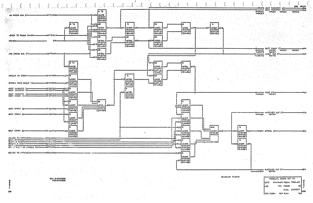
The XC5VLX110T FPGA has 17,280 logic slices available; 2,440 of these are taken by the PCIe interface (for I/O) and DDR2 controller (for main storage), and about 400 are taken by the shift registers to control the lamps and switches, leaving 14,440 for the CPU itself. Of the 3000+ pages of ALD's, I have identified 1315 that need to be translated into VHDL; I have completed 854 of these so far (although they still need lots of testing), and these take up around 5,200 slices. So, it's reasonable to expect that the finished CPU will occupy around 8,000-9,000 slices, which in turn means that the FPGA is very likely to be large enough for our needs.