
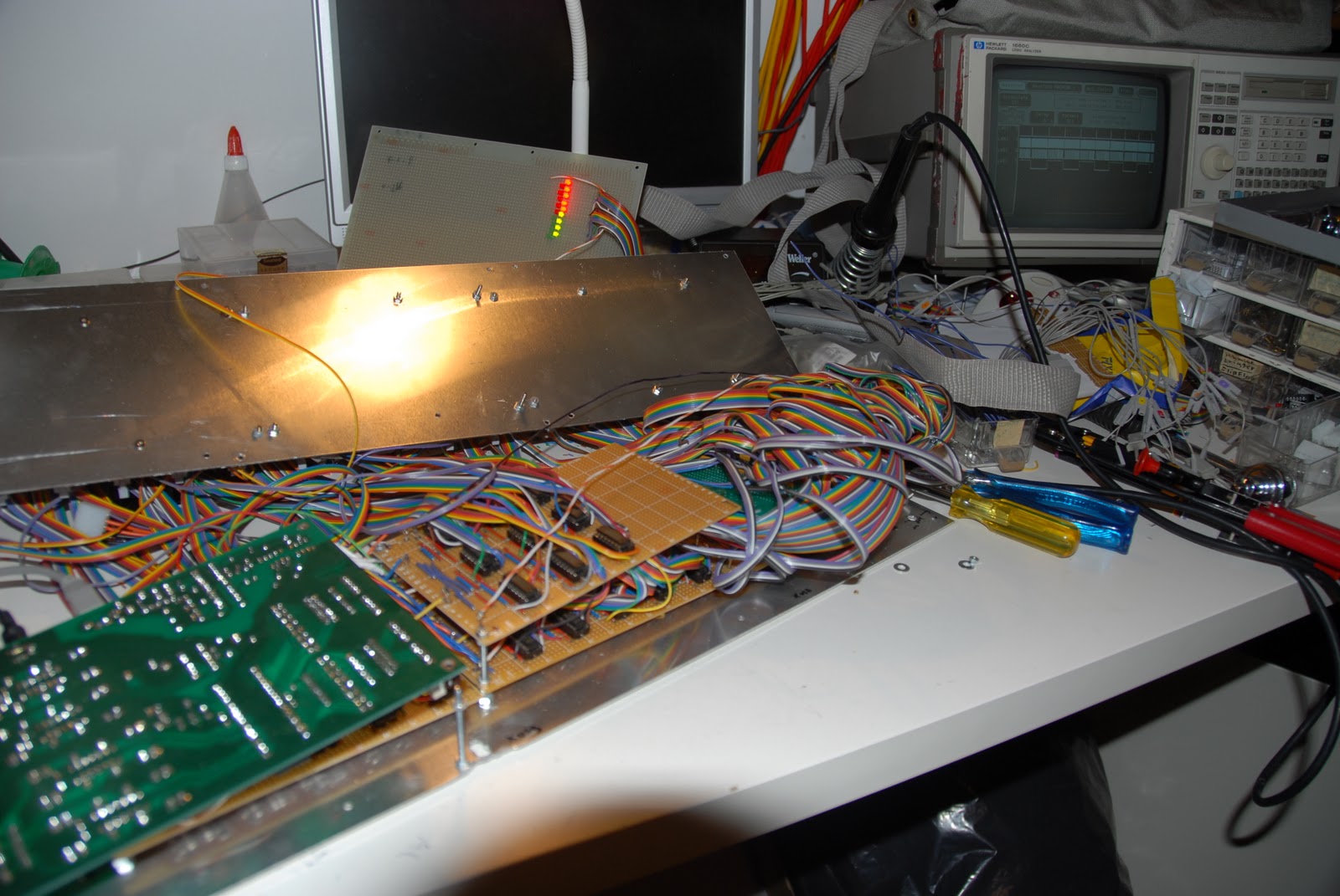
The electronics package is now complete. So, after an initial inspection for obvious problems (no shorts between +5v and ground for instance), it's time to try it out.
I put 18 LEDs on a board along with a flat cable with an IDC connector. I wrote a simple program that would flash all outputs on and off in a checkers pattern. I hooked it all up and... nothing...
So, that means time for troubleshooting. The first problem I found was a short between the CLOCK signal and the +5v on one of the input boards. A tiny amount of solder bridged two tracks on the veroboard. Then I found that the outputs on the Velleman kit needed pull-up resistors. I added those, found out that the outputs were inverting, changed the test program accordingly, and... still no success... Then I found out that I had crossed the outputs to the CLOCK and LATCH signals. I changed the test program to swap those two signals, and voila, the lights started flashing. Next up is testing and if necessary troubleshooting the inputs.
Btw, who else thinks logic analyzers are a godsend?
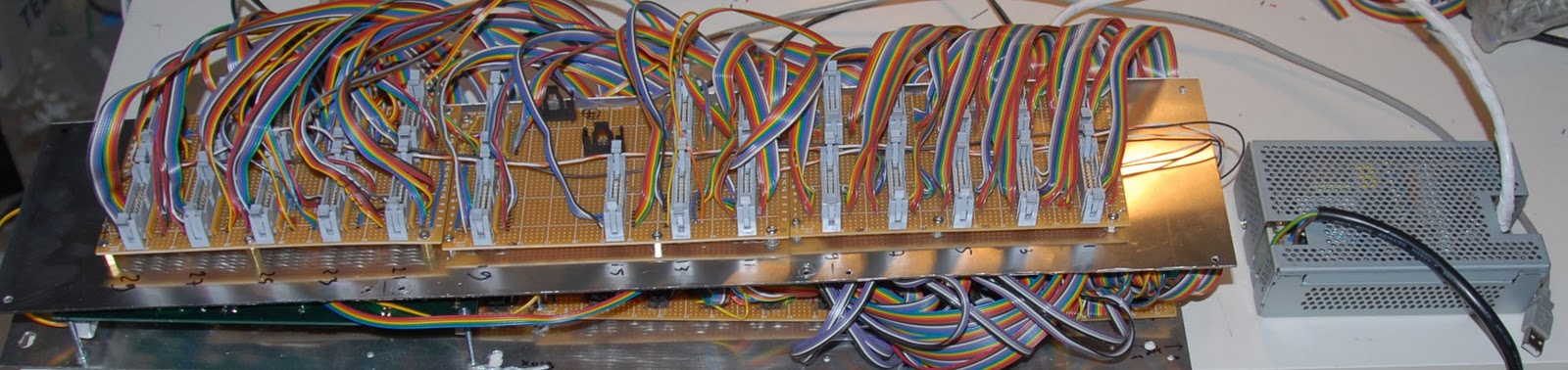
The electronics package now works correctly. The inputs didn't work yet, but I found out that the latch signal was active low. I changed the programming again, and that now works too. The outputs still work with the altered programming, because the output latches are edge triggered.
As you may or may not be able to see in the picture above, The electronics are mounted in two layers of pcb's on an aluminium panel that fits behind the blank panel of the IBM console. The pcb's with the connectors are mounted on a second aluminium panel. I now need to sandwich the two aluminium panels together. To this end, I need some long helical ridges wrapped around steel cylinders, which necessitates making a trip to the hardware store to get some (bolts, that is).