
IBM 360
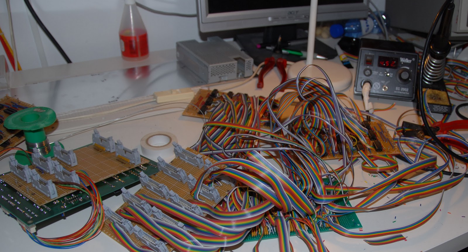
Over half the inter-board connections have been made now. 846 soldering points to be precise. Only 498 to go... Remind me why I picked this hobby again?
- Details
The 360 console panels had a topbar featuring the IBM logo (not striped yet) and "system 360" logo. Unfortunately, it is missing. A system 370 topbar came with the panel, but it doesn't fit. I recreated the design from some photos, so now all I need to do is find an outfit that can print it on aluminium.

- Details
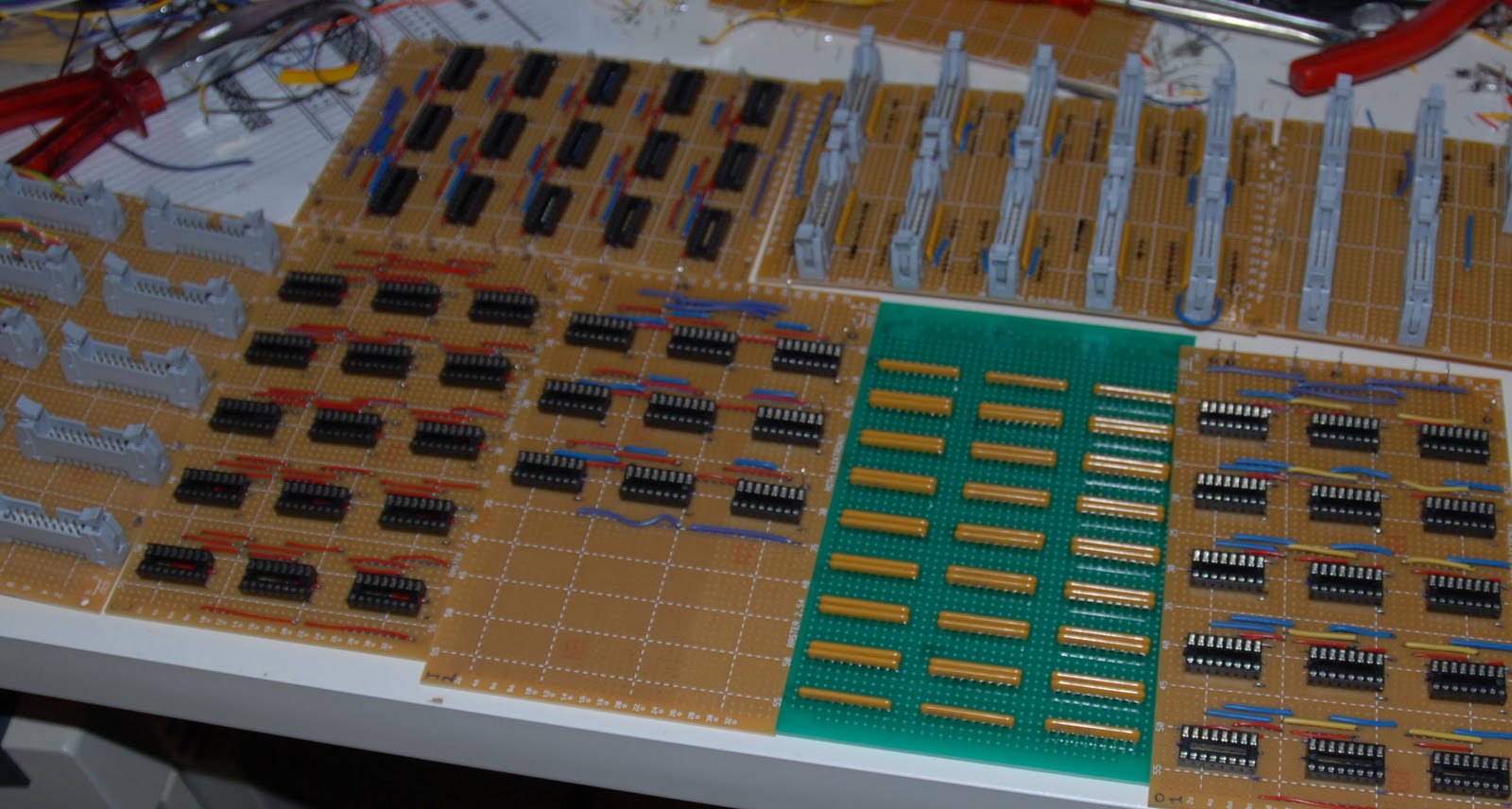
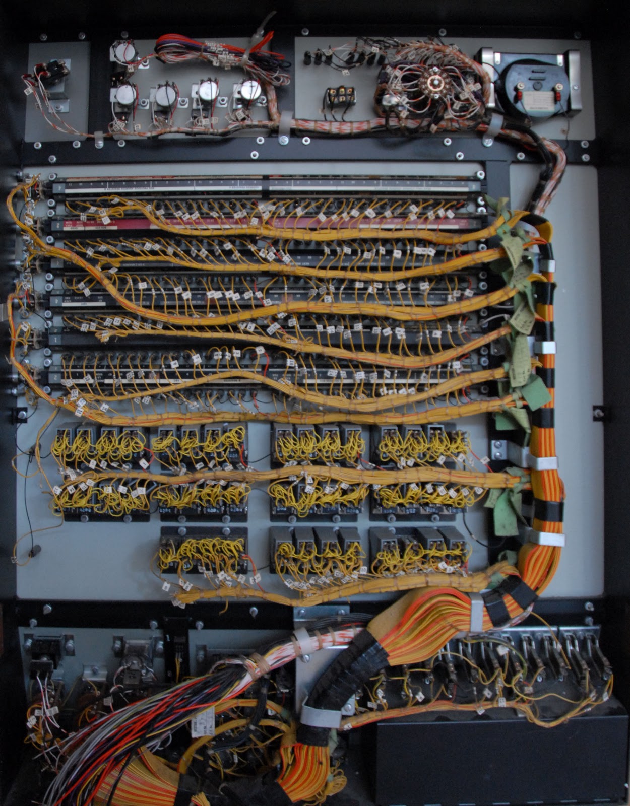
The electronics boards have been completed. The next tedious task will be wiring the eight boards together. Some 700 wires will need to be connected between boards.
- Details
All the panels that need rewiring have been rewired with ribbon cables. The wiring for the main panel was left intact as it was already wired with ribbon cable, so I adopted the existing wiring into my design, and simply put IDC crimp connectors on the end of those cables.
- Details
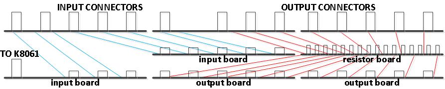
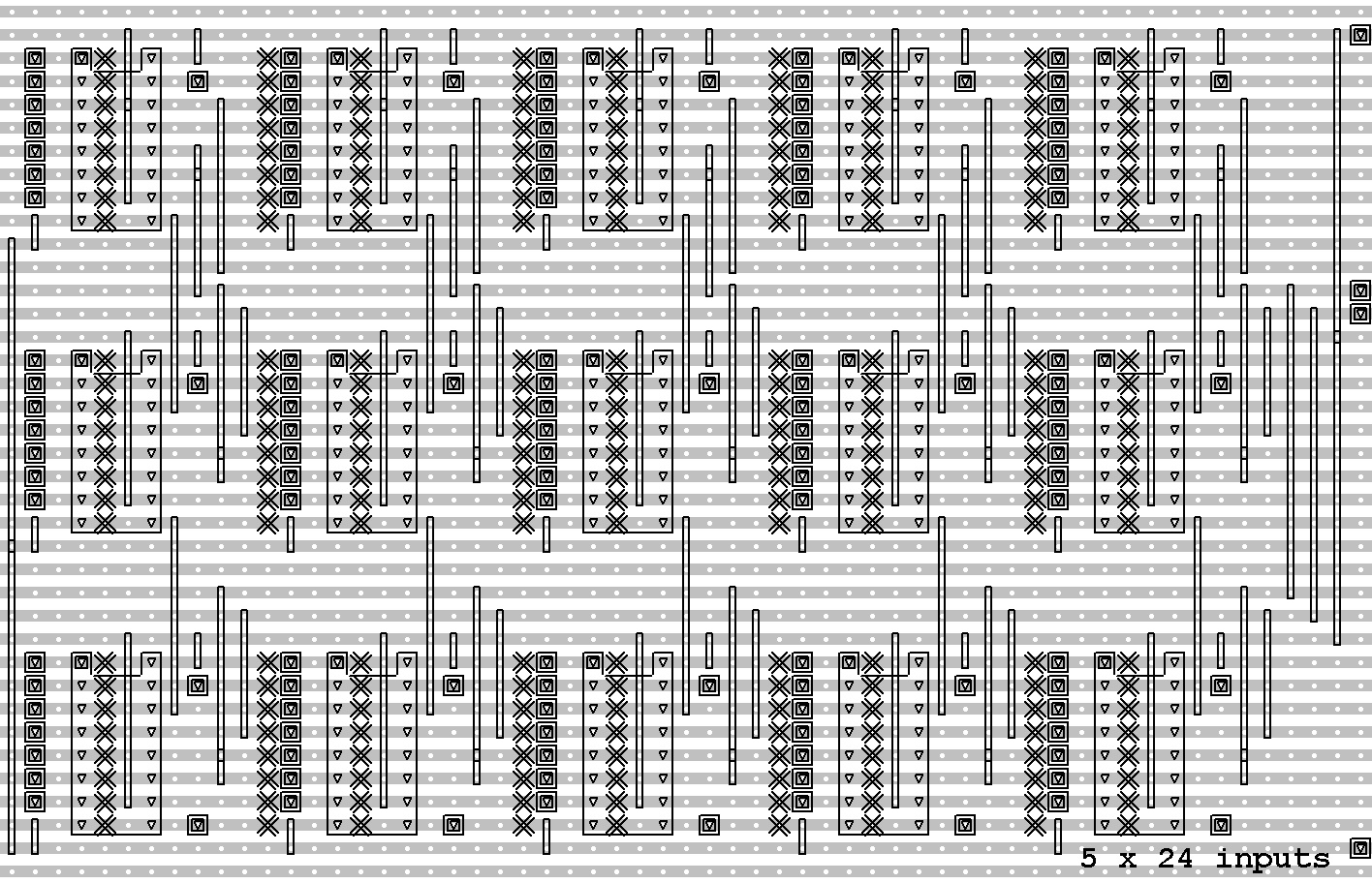
Here are the schematics for the PC interface. As you can see, two of the digital outputs from the K8061 are used to control the shift registers, and the remaining 6 outputs each drive 5 8-bit shift registers for a total of 240 digital outputs.
The 8 digital inputs are each connected to 3 8-bit shift register to record a total of 192 inputs. Five analog inputs are used to record the setting of the five potentiometers, and one analog output is used to drive the voltmeter.
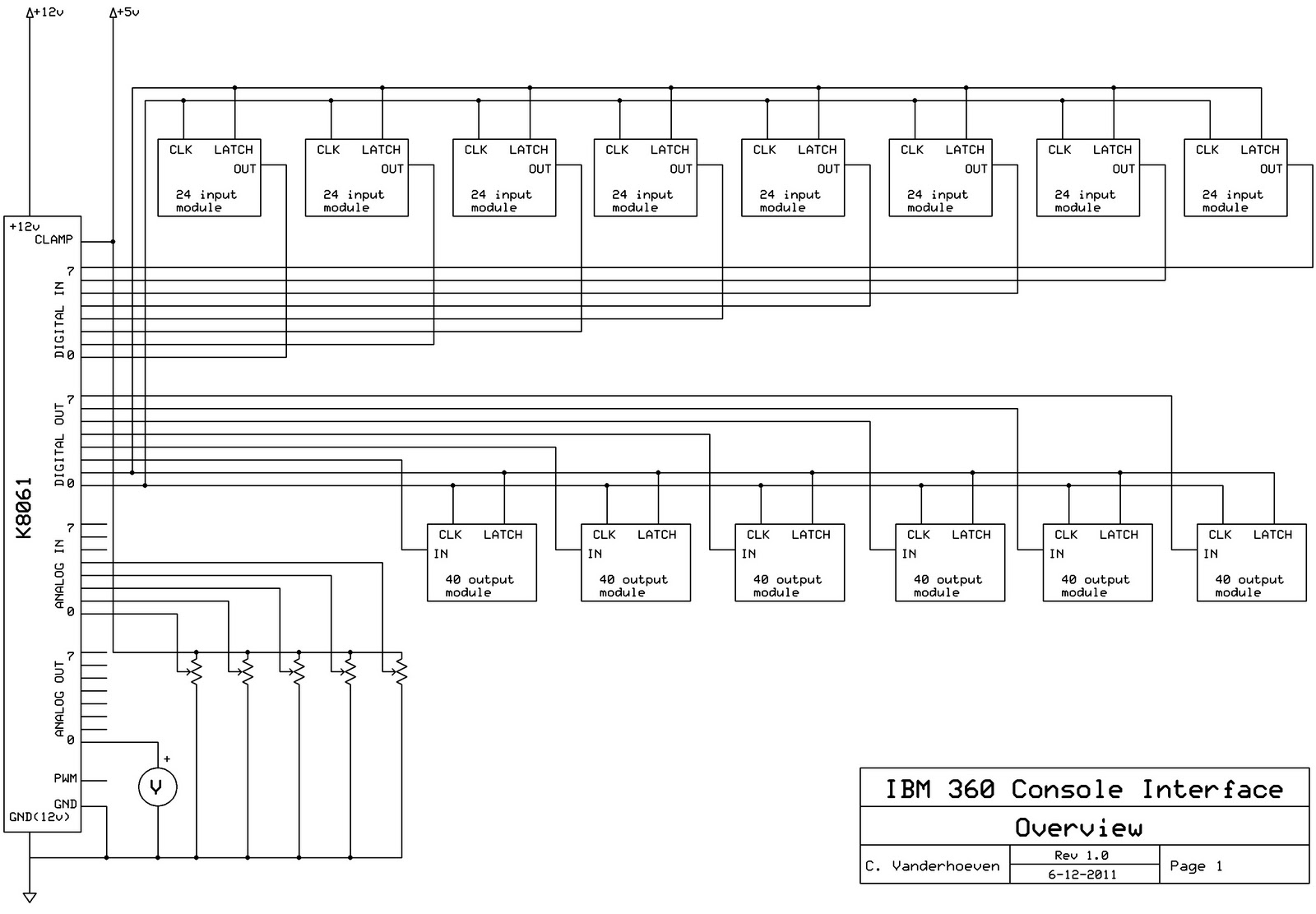
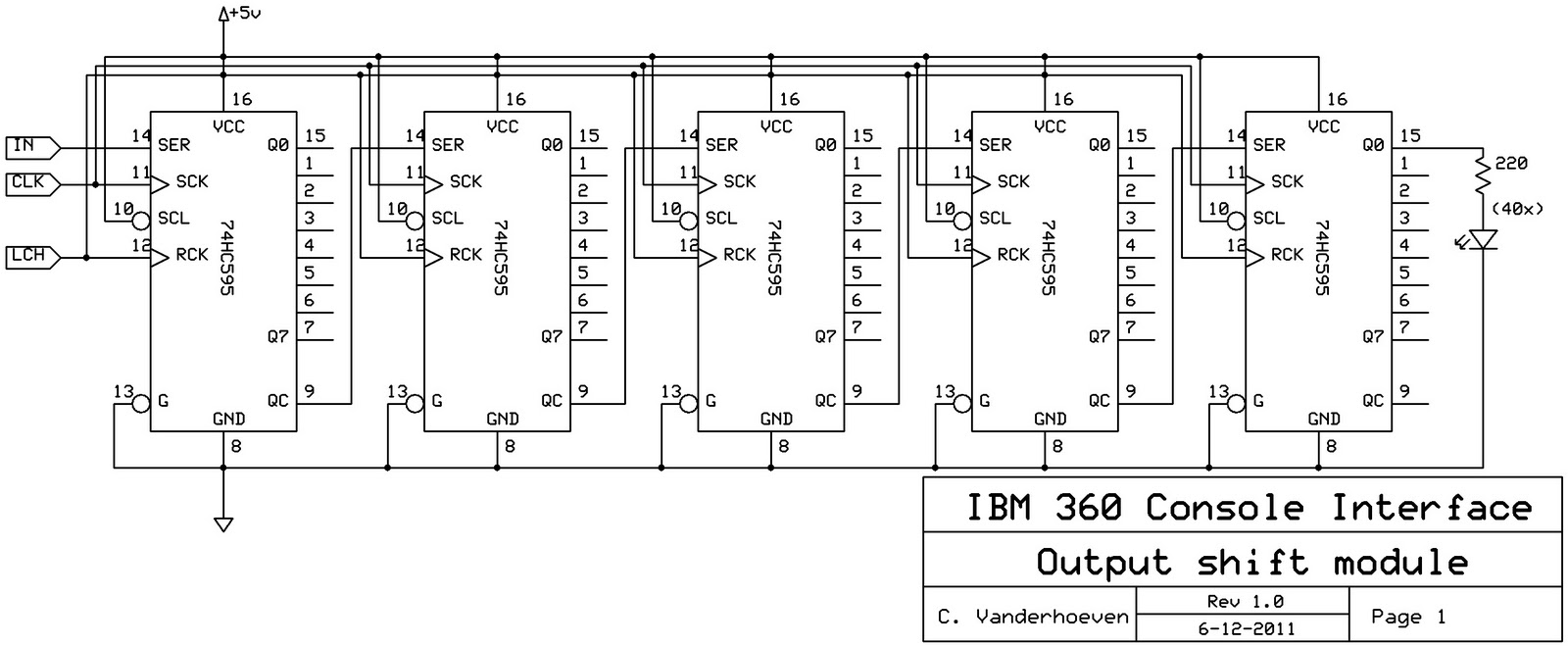
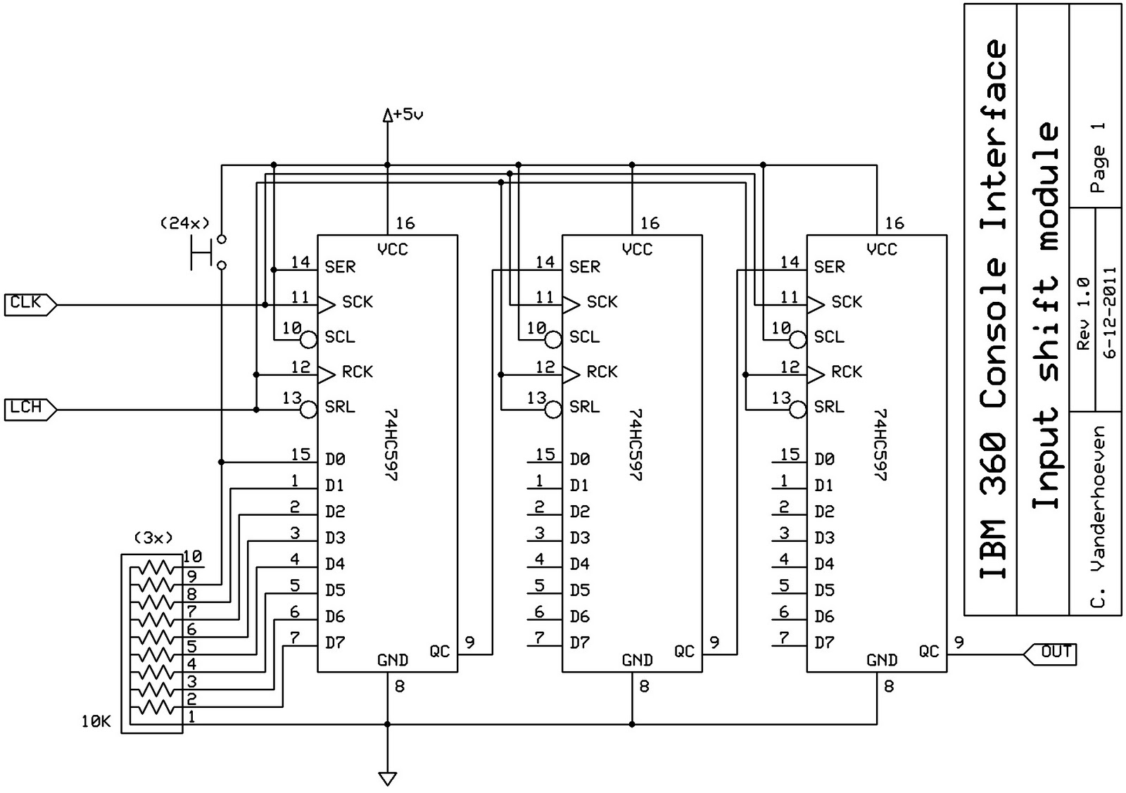
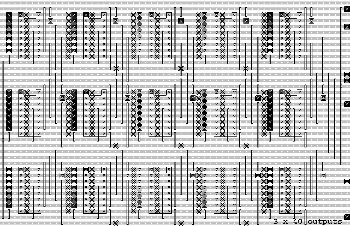
The circuits will be realized on 8 pieces of Veroboard (eurocard size): two for the input shift registers, two for the output shift registers, one for the 220 ohm LED series resistors (using resistor packs), and three for the ribbon cable IDC connectors. The 10K pull-up resistors for the switches are placed on the connector boards.
- Details
All of the panels have been cleaned up. The panel with the dent behind the potentiometer has been straightened out.
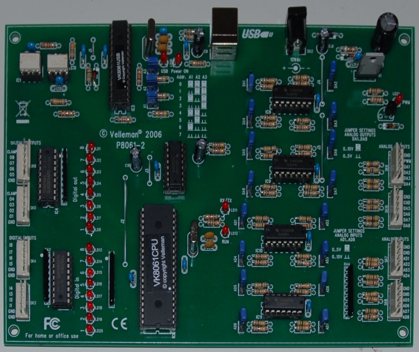
The first part of my order of electronic components came in yesterday. I put together the interface kit and it's functioning correctly.
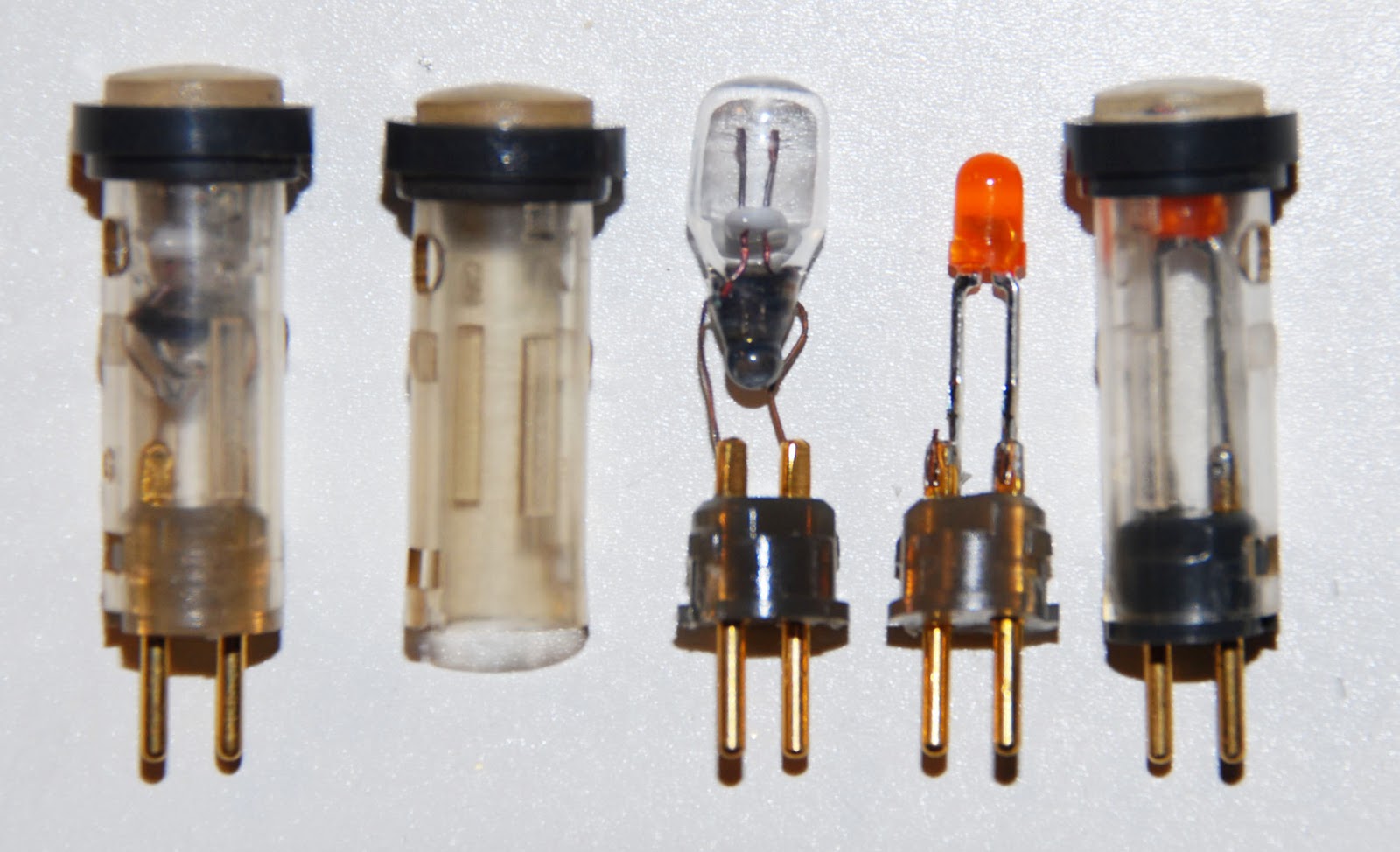
As a test, I've replaced three of the bulbs in the plug-in lamps with orange LEDs. The result looks pretty good. Three done, only 234 to go...
- Details
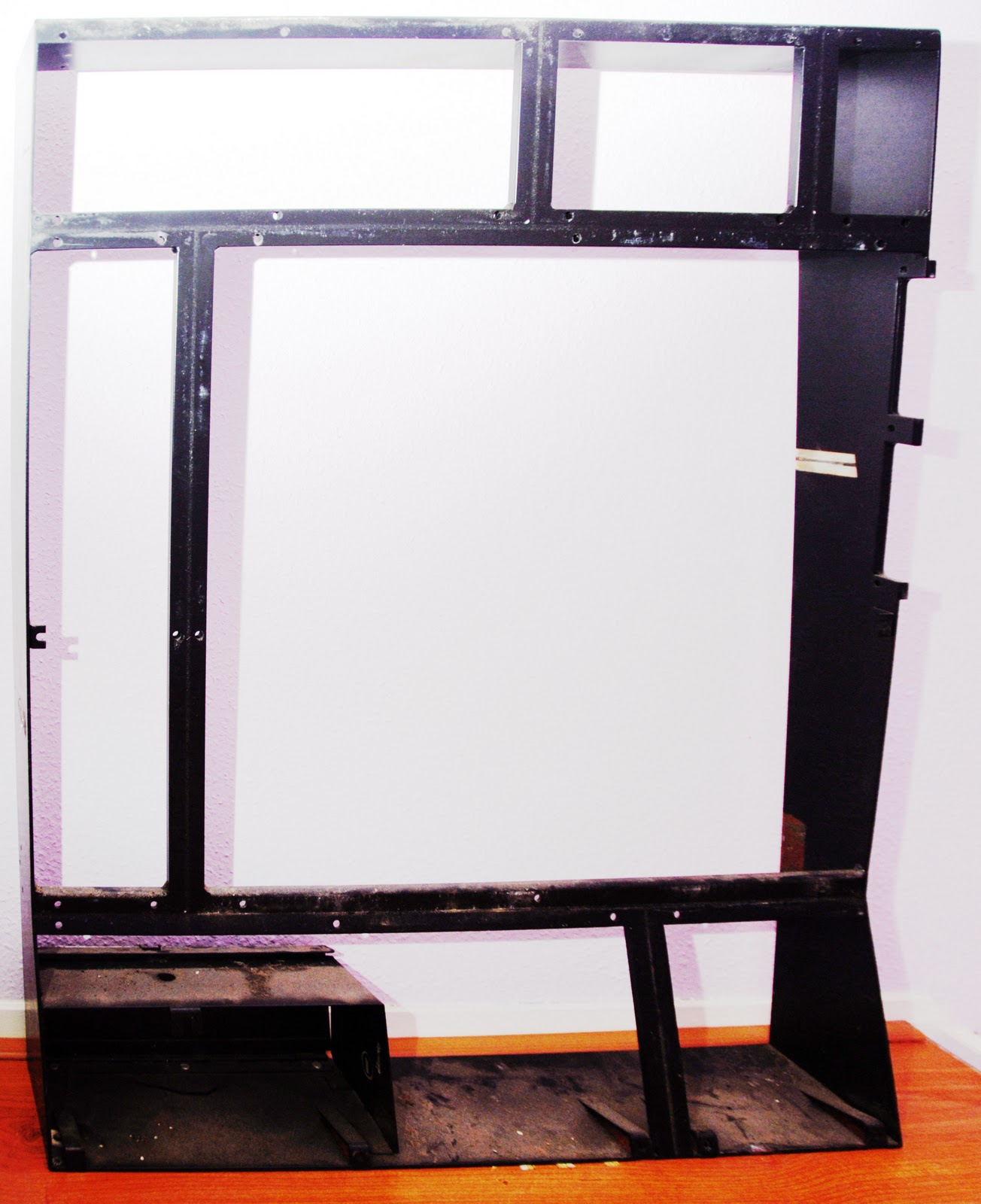
After disassembly, what's left is an empty frame. Unfortunately, all of the panels except for the main panel shown below (register displays and toggle switches) was wired into a single cable harness. To get the panels out, I had to cut the harness, but then, I was going to get rid of it anyway.
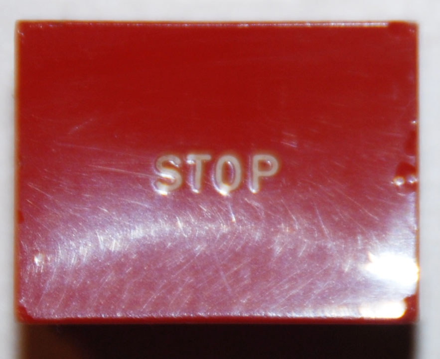
I cleaned all small detachable parts (knobs, button faces) by soaking them in mild laundry detergent overnight. Remember how much tape residue was on the buttons? After cleaning them, they're readable again.
- Details
I thought a bit about the electronics for the console panel. I want to be able to control it remotely from a PC. The PC will need to be able to record input from toggle switches, buttons and rotary controls (potmeters and rotary switches). It will also need to be able to switch the lamps on and off. In total, it will have to provide 183 digital inputs, 237 digital outputs, 5 analog inputs and one analog output (for the voltmeter).
I've opted to use a Velleman K8061 kit. This is a USB interface that provides 8 digital inputs, 8 digital outputs, 8 analog inputs and 8 analog outputs. To control the multitude of switches and lights, I'm going to use shift registers. Lots of them.
The lamps are a bit of a problem. After testing them I found that about half of them are bad and won't light up. They're tiny incandescent bulbs in a plastic casing that plugs into the sockets on the panel. I haven't been able to find replacements for them. Also, the incandescent bulbs would need a buffer stage to connect them to CMOS logic.
Fortunately, the casings are not too hard to open, so I think I'm going to open them up and replace the bulbs with LEDs.
I've just sent off the order for electronics parts to my supplier. I've ordered the Velleman interface kit, a power supply, veroboard, shift registers (74HC595 and 74HC597), orange LEDs, ribbon cable, connectors and a lot of other small items.
- Details
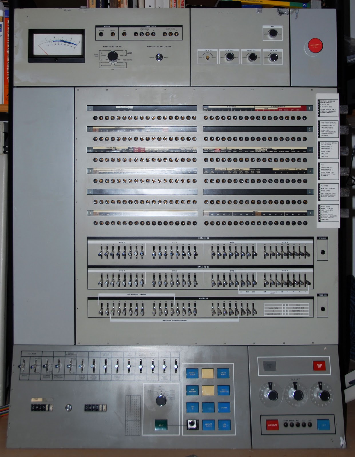
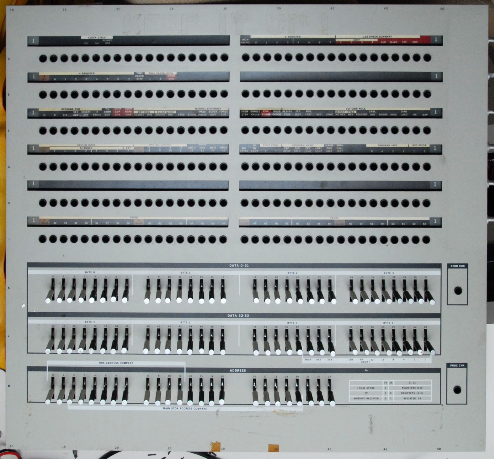
The console panel has been identified as belonging to an IBM 360 model 65 mainframe.
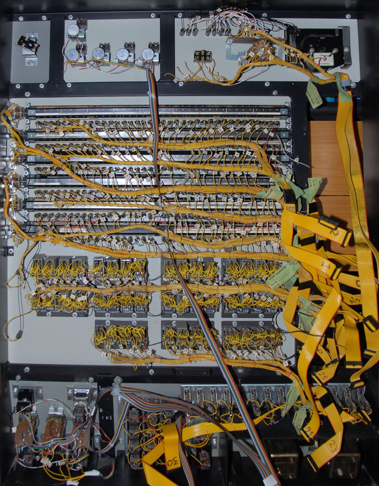
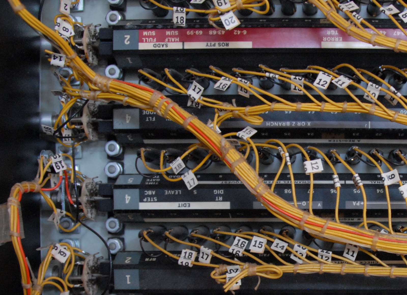
The console panel is divided into sections; each section has it's own steel panel (2.5mm or 0.1" thick) with controls mounted on it. The main panel, which has the register lights and address and data toggle switches on it, is wired using yelow-and-orange ribbon cable. The other panels are wired using a wiring harness with a lot of identical (white-orange striped) wires.
Unfortunately, the cables were simply chopped off when the console panel was separated from the cpu. This makes it hard to determine which wire is which. At the console end of the cables, every wire is individually numbered as shown below.
So, the plan is as follows:
- disassemble the panel
- clean up the individual bits and pieces
- rewire the bits that need re-wiring (all the bits that don't use the ribbon cables)
- reassemble the panel
- add some electronics to control the lights and switches from a pc
- create a software interface between the panel and a Hercules emulator running on the pc
- Details

On the morning of the 29th of November, a long awaited pallet arrived at my doorstep. Inside? An IBM 360 mainframe's console panel from the 1960's. This particular one spent part of its life on the desk of a software engineer at Digital Equipment Corporation, IBM's main competitor in that era.
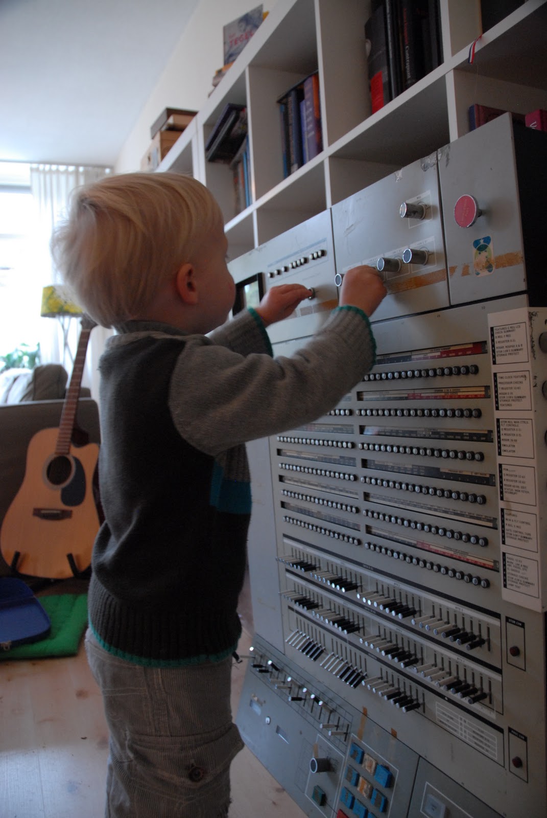
Upon arrival, the contents of the package were seized by our two year old son Ties. I don't believe he left a knob unturned, button unpushed or switch untoggled.
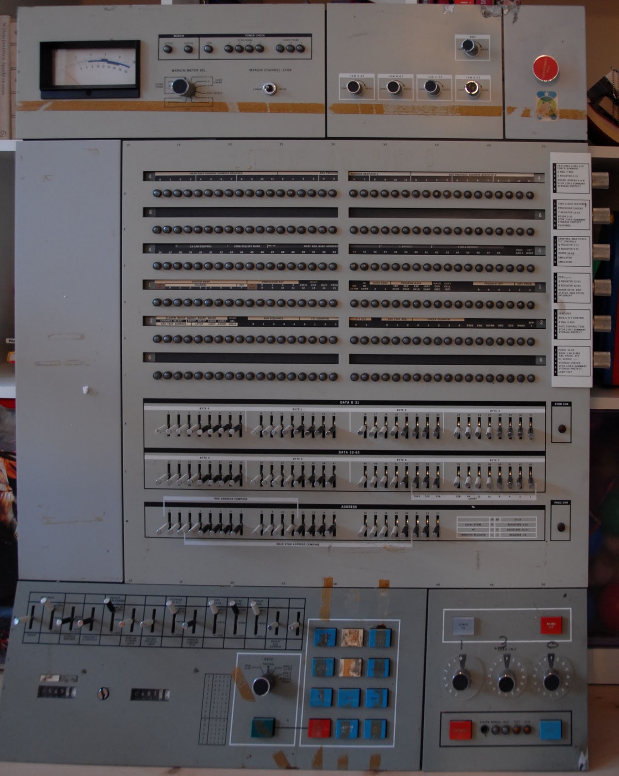
As is seen more clearly in the big image below, there is some damage to the panel (note the potentiometer near the upper right corner, it's at an odd angle), and there is some tape residue left behind. On most of the buttons, the text can't be read anymore.
- Details