One of my projects is to emulate the Philips X1215 cartridge disc drive (at the drive level, so the emulator connects to the original CDD controller).
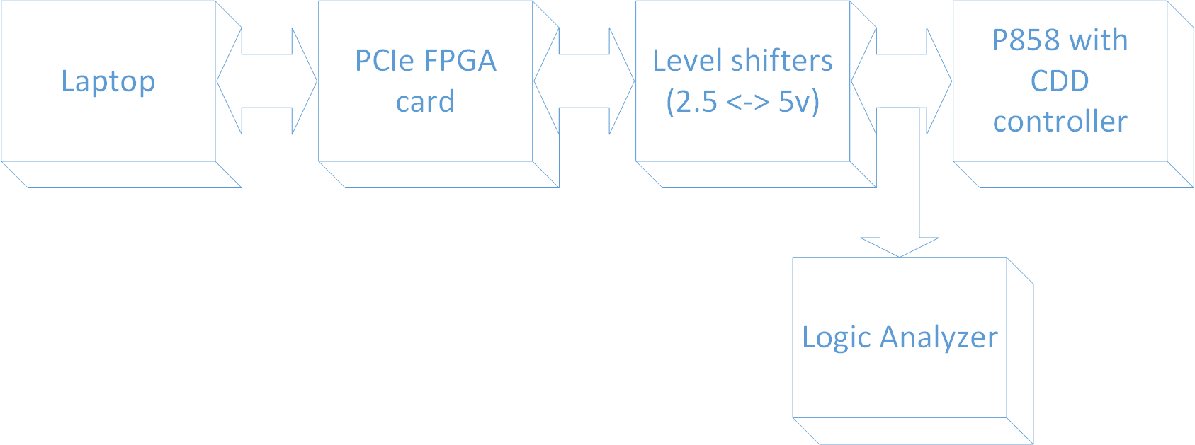
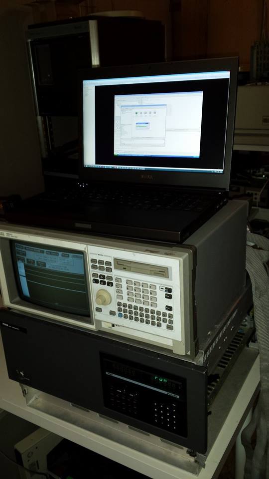
The system consists of a laptop with a special driver and program on it, an FPGA card that is programmed to emulate the disk, some level shifters to provide I/O at the 5 volts level the controller operates at, and a cable to connect the level shifters to the controller. The cable has an extra connector on it to easily attach a logic analyzer for debugging purposes.
The chain between the disk image (sitting on a PC) and the P800 is as follows:
- Disk image on PC
- Disk serving application on PC
- PCIe bus
- FPGA card
- Level converters (3.3v <==> 5v)
- Cable
- CDD X1215 control unit in P800
- P800 CPU
Disk image on PC
The disk image is a binary file that simply contains the data found on a disk pack. So, it's got 2 * 204 * 16 blocks that are each 410 bytes long. Theo Engel has some images available for download from his site.
Disk serving application on PC
This is a fairly simple application that communicates with the FPGA over the PC's PCIe bus. It presents a simple dialog; something like this:
| X1215 DISK SERVER v0.0 Fixed disk? C:\P800\disk0.img Unit off-line, load a cartridge to bring it on-line or type EXIT Cartridge? C:\P800\disk1.img Unit on-line, type YES to take unit off-line Off-line? YES Unit off-line, load a cartridge to bring it on-line or type EXIT Cartridge? C:\P800\disk2.img File does not exist. Do you want to create a new image? YES Unit on-line, type YES to take unit off-line Off-line? YES Unit off-line, load a cartridge to bring it on-line or type EXIT Cartridge? EXIT Bye bye |
Communication with the FPGA is through a 32KB memory range. This range is divided into 4 * 16 512-byte blocks. This is enough to contain all the data for one track on both the fixed and the removable platters at once. This way, the memory only needs to be updated when a SEEK is issued, which the controller expects to take some time.Of course, only 410 bytes out of each 512 byte block are actually used for data. One 32-bit word in the unused area is used for status communication.
<OPERATION
- When the disk serving application starts, it loads the track 0 data into the FPGA, then writes data to the status word to inform the FPGA that a) the disk is online and that b) data has been loaded for track 0.
- If a seek is issued by the control unit, the FPGA signals this to the application by changing the track number to the one needed. If the previous track has been written to, a dirty flag is set in the status word.
- When the application sees the changed track number, it examines the dirty flag. If it is set, the data from the FPGA is read back to the application's copy of the disk images.
- The application now loads the data for the new track into the FPGA. It signals the FPGA by writing the new track number to the status word.
- When the user opts to unload the cartridge, the PC signals the FPGA that the unit goes off-line. It then checks the dirty flag and reads back the track data if needed. It then closes the disk image file after updating it.
FPGA Card
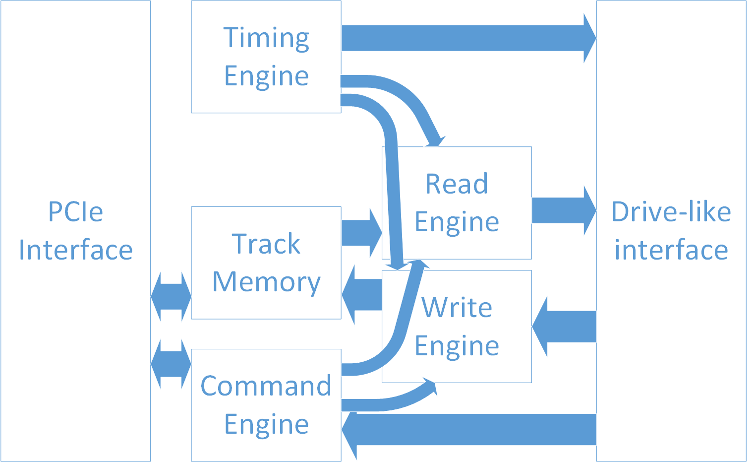
The FPGA card is the heart of the emulated disk drive. It responds to commands from the control unit by instructing the application to perform seeks, selecting the right head, and performing read and write operations. It properly serializes data for reading, and unserializes data for writing. It provides all the necessary timing signals (sector and index pulses) to the control unit.
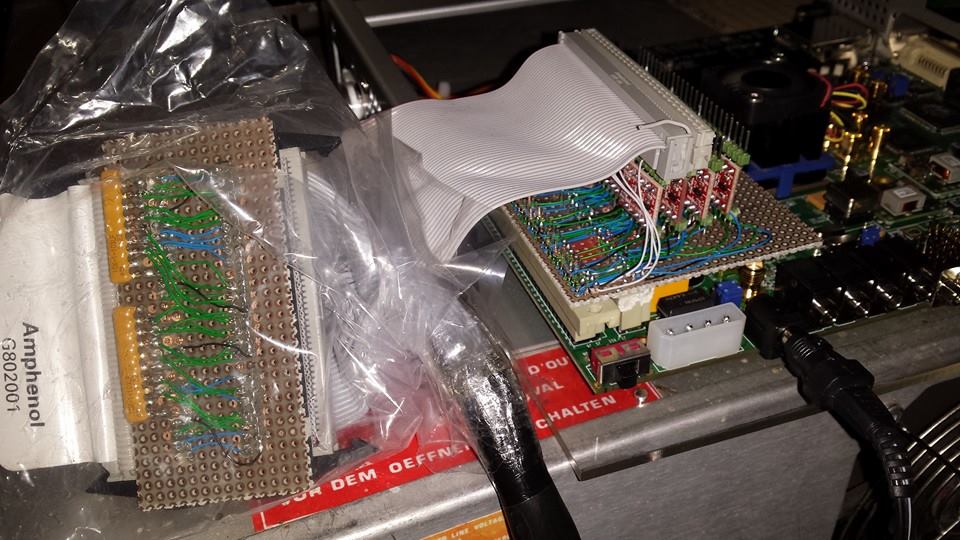
The FPGA card used is a Xilinx XUPV5.
Level converters
These are necessary because the FPGA uses 3.3 volts for a logic "1", and the control unit uses 5 volts for a logic "1". I'm building a sandwiched interface card that sits on top of the FPGA card, containing 64 level converters (more than is needed here, but I like the flexibility so I can use it for more projects requiring more pins). I'm building it out of perfboard, using wire-wrap technique to connect the converters to the connectors.
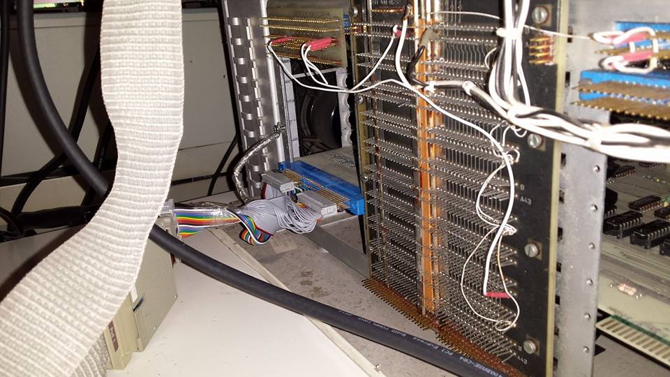
Cable
This is a custom-made cable that has a 50-pin IDC connector on one end (to connect to the level converter board), and a 74-pin card edge connector on the other end (to connect to the CDD). Why Philips couldn't use a more common connector size is beyond me!
The cable has also been fitted with two 20-pin IDC connectors for direct connection to my logic analyzer.
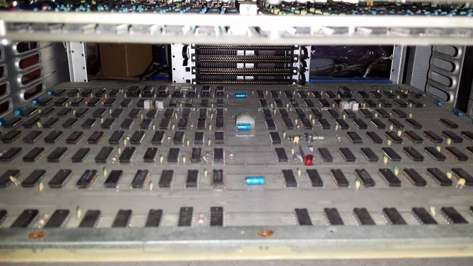
P800 and CDD
The P800 and CDD themselves remain completely unchanged. The emulator connects to the CDD the same way a real X1215 would.